AMP cloud is configured to report AMP Connector scan events from windows machines belong to “Audit” group to MFC but the scanned events are not showing up in FMC, what could be the possible cause?
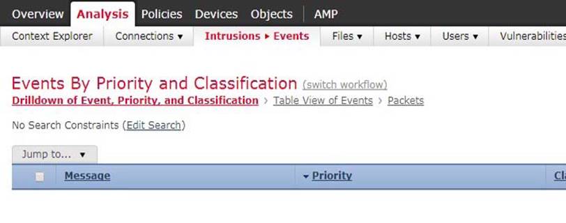
Refer to the exhibit.

AMP cloud is configured to report AMP Connector scan events from windows machines belong to “Audit” group to MFC but the scanned events are not showing up in FMC, what could be the possible cause?
A . DNS address is misconfigured on FM
C . FMC is pointing to incorrect AMP cloud address
D . AMP could is pointing to incorrect FMC address
E . Event should be viewed as “Malware” event in FM
G . Possible issue with certificate download from AMP cloud for FMC integration.
H . Incorrect group is selected for the events export in AMP cloud for FMC
Answer: D
Latest 400-251 Dumps Valid Version with 124 Q&As
Latest And Valid Q&A | Instant Download | Once Fail, Full Refund
Subscribe
Login
0 Comments
Inline Feedbacks
View all comments

