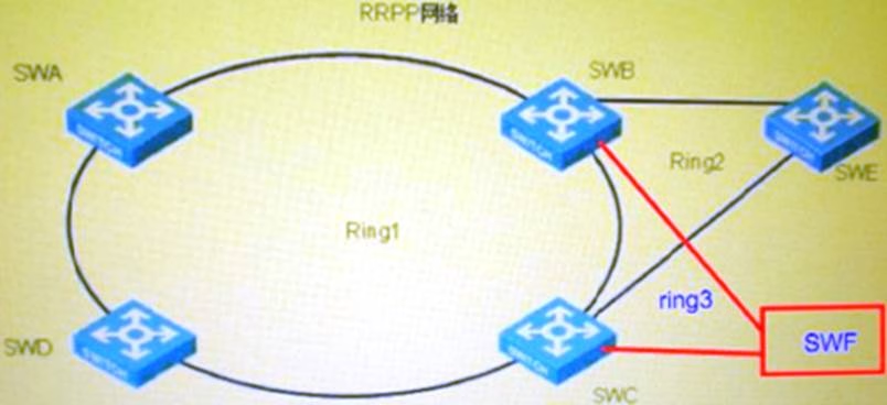
The figure shows the networking application of RRPP. The switches SWA, SWB, SWC, and SWD in the customer LAN form the main ring 1 of the RRPP ring. The switches SWB, SWC, and SWE form the sub-ring 2. The switches SWB, SWC, and sWF form the sub-ring 3. If the switch SWE is the master node of the sub-ring 2 and SWF is the master node of the sub-ring 3, What can we learn from the above information?
A . It is not possible to add sub-ring 2 and sub-ring 3 to the same ring group.
B . If sub-ring 2 and sub-ring 3 are added to the same ring group, the edge nodes and auxiliary edge nodes of sub-ring 2 and sub-ring 3 in the ring group can be different
C . If sub-ring 2 and sub-ring 3 are added to the same ring group, the ring groups should be configured on the switches SWB, SWC, SWE, and SWF respectively and the configurations should be consistent.
D . If sub-ring 2 and sub-ring 3 are added to the same ring group, the primary ring links corresponding to the edge nodes and auxiliary edge nodes of sub-ring 2 and sub-ring 3 in the ring group should be consistent.
Answer: D
Latest GB0-372-ENU Dumps Valid Version with 432 Q&As
Latest And Valid Q&A | Instant Download | Once Fail, Full Refund
