

You are enabling advanced policy-based routing. You have configured a static route that has a next hop from the inet.0 routing table. Unfortunately, this static route is not active in your routing instance.
In this scenario, which solution is needed to use this next hop?
- A . Use RIB groups.
- B . Use filter-based forwarding.
- C . Use transparent mode.
- D . Use policies.
A
Explanation:
To enable advanced policy-based routing in Junos OS and activate a static route with a next-hop address in the inet.0 table within your routing instance, you should utilize RIB groups. RIB groups allow you to import routes from one routing table to another. In this scenario, the static route within the routing instance needs access to the inet.0 routes, which is facilitated by configuring a RIB group. Juniper’s documentation outlines RIB groups as a necessary component for handling instances where routes need to be shared across routing tables, thereby ensuring seamless traffic flow through specified routes. For more details, refer to the Juniper Networks Documentation on RIB Groups.
In Junos OS for SRX Series devices, when enabling advanced policy-based routing and configuring a static route with a next-hop from the inet.0 routing table, the issue arises because the static route is not being used in the routing instance. This is a common scenario when the next-hop belongs to a different routing table or instance, and the routing instance is not aware of that next-hop.
To resolve this, RIB (Routing Information Base) groups are used. RIB groups allow routes from one routing table (RIB) to be shared or imported into another routing table. This means that the routing instance can import the necessary routes from inet.0 and make them available for the routing instance where the policy-based routing is applied.
Detailed Steps:
Configure the Static Route: First, configure the static route pointing to the next-hop in inet.0.
Here’s an example:
bash set routing-options static route 10.1.1.0/24 next-hop 192.168.1.1 This static route will be placed in the inet.0 routing table by default.
Create and Apply a RIB Group: To import routes from inet.0 into the routing instance, create a RIB group configuration. This will allow the static route from inet.0 to be visible within the routing instance.
Example configuration for the RIB group:
bash
set routing-options rib-groups RIB-GROUP import-rib inet.0
set routing-options rib-groups RIB-GROUP import-rib <routing-instance-name>.inet.0
This configuration ensures that routes from inet.0 are imported into the specified routing instance.
Apply the RIB Group to the Routing Instance:
Once the RIB group is configured, apply it to the appropriate routing instance:
bash
set routing-instances <routing-instance-name> routing-options rib-group RIB-GROUP
Verify Configuration: Use the following command to verify that the static route has been imported
into the routing instance:
bash
show route table <routing-instance-name>.inet.0
The output should now display the static route imported from inet.0.
Juniper Security
Reference: RIB Groups Overview: Juniper’s documentation provides detailed information on how RIB groups function and how to use them to share routes between different routing tables. This is essential for scenarios involving policy-based routing where routes from one instance (like inet.0) need to be available in another instance.
Reference: Juniper Networks Documentation on RIB Groups.
By using RIB groups, you ensure that the static route from inet.0 is available in the appropriate routing instance for policy-based routing to function correctly. This avoids the need for other methods like filter-based forwarding or transparent mode, which do not address the specific issue of static route visibility across routing instances.
Exhibit:
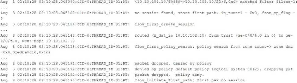

Referring to the flow logs exhibit, which two statements are correct? (Choose two.)
- A . The packet is dropped by the default security policy.
- B . The packet is dropped by a configured security policy.
- C . The data shown requires a traceoptions flag of host-traffic.
- D . The data shown requires a traceoptions flag of basic-datapath.
AD
Explanation:
Understanding the Flow Log Output:
From the flow logs in the exhibit, we can observe the following key events:
The session creation was initiated (flow_first_create_session), but the policy search failed (flow_first_policy_search), which implies that no matching policy was found between the zones involved (zone trust-> zone dmz).
The packet was dropped with the reason "denied by policy." This shows that the packet was dropped either due to no matching security policy or because the default policy denies the traffic (packet dropped, denied by policy).
The line denied by policy default-policy-logical-system-00(2) indicates that the default security policy is responsible for denying the traffic, confirming that no explicit security policy was configured to allow this traffic.
Explanation of Answer A (Dropped by the default security policy):
The log message clearly states that the packet was dropped by the default security policy (default-policy-logical-system-00). In Junos, when a session is attempted between two zones and no explicit policy exists to allow the traffic, the default policy is to deny the traffic. This is a common behavior in Junos OS when a security policy does not explicitly allow traffic between zones. Explanation of Answer D (Requires traceoptions flag of basic-datapath):
The information displayed in the log involves session creation, flow policy search, and packet dropping due to policy violations, which are all part of basic packet processing in the data path. This type of information is logged when the traceoptions flag is set to basic-datapath. The basic-datapath traceoption provides detailed information about the forwarding process, including policy lookups and packet drops, which is precisely what we see in the exhibit.
The traceoptions flag host-traffic (Answer C) is incorrect because host-traffic is typically used for traffic destined to or generated from the Junos device itself (e.g., SSH or SNMP traffic to the SRX device), not for traffic passing through the device.
To capture flow processing details like those shown, you need the basic-datapath traceoptions flag, which provides details about packet forwarding and policy evaluation.
Step-by-Step Configuration for Tracing (Basic-Datapath):
Enable flow traceoptions:
To capture detailed information about how traffic is being processed, including policy lookups and flow session creation, enable traceoptions for the flow. bash
set security flow traceoptions file flow-log
set security flow traceoptions flag basic-datapath
Apply the configuration and commit:
bash
commit
View the logs:
Once enabled, you can check the trace logs for packet flows, policy lookups, and session creation details:
bash
show log flow-log
This log will contain information similar to the exhibit, including session creation attempts and
packet drops due to security policy.
Juniper Security
Reference: Default Security Policies: Juniper SRX devices have a default security policy to deny all traffic that is not explicitly allowed by user-defined policies. This is essential for security best practices.
Reference: Juniper Networks Documentation on Security Policies.
Traceoptions for Debugging Flows: Using traceoptions is crucial for debugging and understanding how traffic is handled by the SRX, particularly when issues arise from policy misconfigurations or routing.
Reference: Juniper Traceoptions.
By using the basic-datapath traceoptions, you can gain insights into how the device processes traffic, including policy lookups, route lookups, and packet drops, as demonstrated in the exhibit.
Exhibit:
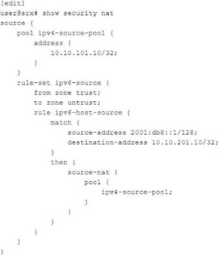

You are configuring NAT64 on your SRX Series device. You have committed the configuration shown in the exhibit. Unfortunately, the communication with the 10.10.201.10 server is not working. You have verified that the interfaces, security zones, and security policies are all correctly configured.
In this scenario, which action will solve this issue?
- A . Configure source NAT to translate return traffic from IPv4 address to the IPv6 address of your source device.
- B . Configure proxy-ARP on the external IPv4 interface for the 10.10.201.10/32 address.
- C . Configure proxy-NDP on the IPv6 interface for the 2001:db8::1/128 address.
- D . Configure destination NAT to translate return traffic from the IPv4 address to the IPv6 address of your source device.
What are three core components for enabling advanced policy-based routing? (Choose three.)
- A . Filter-based forwarding
- B . Routing options
- C . Routing instance
- D . APBR profile
- E . Policies
ACD
Explanation:
To enable Advanced Policy-Based Routing (APBR) on SRX Series devices, three key components are necessary: filter-based forwarding, routing instances, and APBR profiles. Filter-based forwarding is utilized to direct specific traffic flows to a routing instance based on criteria set by a policy. Routing instances allow the traffic to be managed independently of the main routing table, and APBR profiles define how and when traffic should be forwarded. These elements ensure that APBR is flexible and tailored to the network’s requirements. Refer to Juniper’s APBR Documentation for more details.
Advanced policy-based routing (APBR) in Juniper’s SRX devices allows the selection of different paths for traffic based on policies, rather than relying purely on routing tables.
To enable APBR, the following core components are required:
Filter-based Forwarding (Answer A): Filter-based forwarding (FBF) is a technique used to forward traffic based on policies rather than the default routing table. It is essential for enabling APBR, as it helps match traffic based on filters and directs it to specific routes.
Configuration Example:
bash
set firewall family inet filter FBF match-term source-address 192.168.1.0/24 set firewall family inet filter FBF then routing-instance custom-routing-instance
Routing Instance (Answer C): A routing instance is required to define the separate routing table used by APBR. You can create multiple routing instances and assign traffic to these instances based on policies. The traffic will then use the routes defined within the specific routing instance.
Configuration Example:
bash
set routing-instances custom-routing-instance instance-type forwarding
set routing-instances custom-routing-instance routing-options static route 0.0.0.0/0 next-hop 10.10.10.1
APBR Profile (Answer D): The APBR profile defines the rules and policies for advanced policy-based routing. It allows you to set up conditions such as traffic type, source/destination address, and port, and then assign actions such as redirecting traffic to specific routing instances.
Configuration Example:
bash
set security forwarding-options advanced-policy-based-routing profile apbr-profile match application http
set security forwarding-options advanced-policy-based-routing profile apbr-profile then routing-instance custom-routing-instance
Other Components:
Routing Options (Answer B) are not a core component of APBR, as routing options define the general behavior of the routing table and protocols. However, APBR works by overriding these default routing behaviors using policies.
Policies (Answer E) are crucial in many network configurations but are not a core component of enabling APBR. APBR specifically relies on profiles rather than standard security policies. Juniper Security
Reference: Advanced Policy-Based Routing (APBR): Juniper’s APBR is a powerful tool that allows routing based on specific traffic characteristics rather than relying on static routing tables. APBR ensures that specific types of traffic can take alternate paths based on business or network needs.
Reference: Juniper Networks APBR Documentation.
You want to bypass IDP for traffic destined to social media sites using APBR, but it is not working and IDP is dropping the session.
What are two reasons for this problem? (Choose two.)
- A . The session did not properly reclassify midstream to the correct APBR rule.
- B . IDP disable is not configured on the APBR rule.
- C . The application services bypass is not configured on the APBR rule.
- D . The APBR rule does a match on the first packet.
AC
Explanation:
Explanation of Answer A (Session Reclassification):
APBR (Advanced Policy-Based Routing) requires the session to be classified based on the specified rule, which can change midstream as additional packets are processed. If the session was already established before the APBR rule took effect, the traffic may not be correctly reclassified to match the new APBR rule, leading to IDP (Intrusion Detection and Prevention) processing instead of being bypassed. This can occur especially when the session was already established before the rule change. Explanation of Answer C (Application Services Bypass):
For APBR to work and bypass the IDP service, the application services bypass must be explicitly configured. Without this configuration, the APBR rule may redirect the traffic, but the IDP service will still inspect and potentially drop the traffic. This is especially important for traffic destined for specific sites like social media platforms where bypassing IDP is desired. Example configuration for bypassing IDP services:
bash
set security forwarding-options advanced-policy-based-routing profile <profile-name> application-services-bypass
Step-by-Step Resolution:
Reclassify the Session Midstream:
If the traffic was already being processed before the APBR rule was applied, ensure that the session is
reclassified by terminating the current session or ensuring the APBR rule is applied from the start.
Command to clear the session:
bash
clear security flow session destination-prefix <ip-address>
Configure Application Services Bypass:
Ensure that the APBR rule includes the application services bypass configuration to properly bypass
IDP or any other security services for traffic that should not be inspected.
Example configuration:
bash
set security forwarding-options advanced-policy-based-routing profile <profile-name> application-services-bypass
Juniper Security
Reference: Session Reclassification in APBR: APBR requires reclassification of sessions in real-time to ensure midstream packets are processed by the correct rule. This is crucial when policies change dynamically or new rules are added.
Application Services Bypass in APBR: This feature ensures that security services such as IDP are bypassed for traffic that matches specific APBR rules. This is essential for applications where performance is a priority and security inspection is not necessary.
Which two statements are correct about mixed mode? (Choose two.)
- A . Layer 2 and Layer 3 interfaces can use the same security zone.
- B . IRB interfaces can be used to route traffic.
- C . Layer 2 and Layer 3 interfaces can use separate security zones.
- D . IRB interfaces cannot be used to route traffic.
Exhibit:
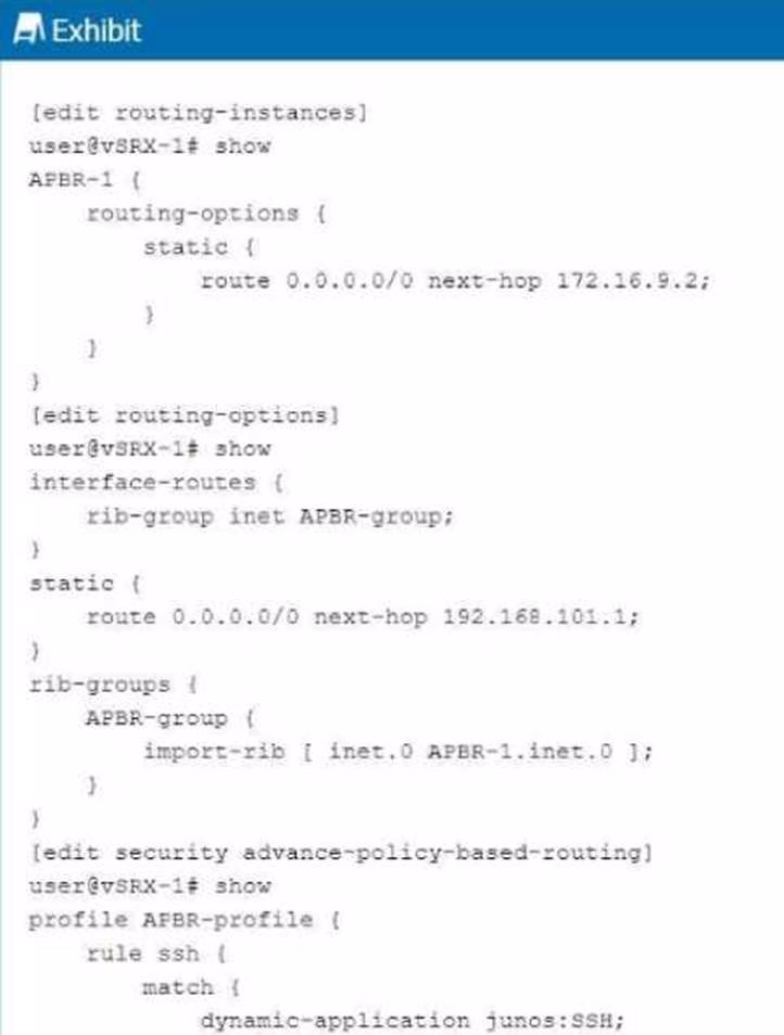

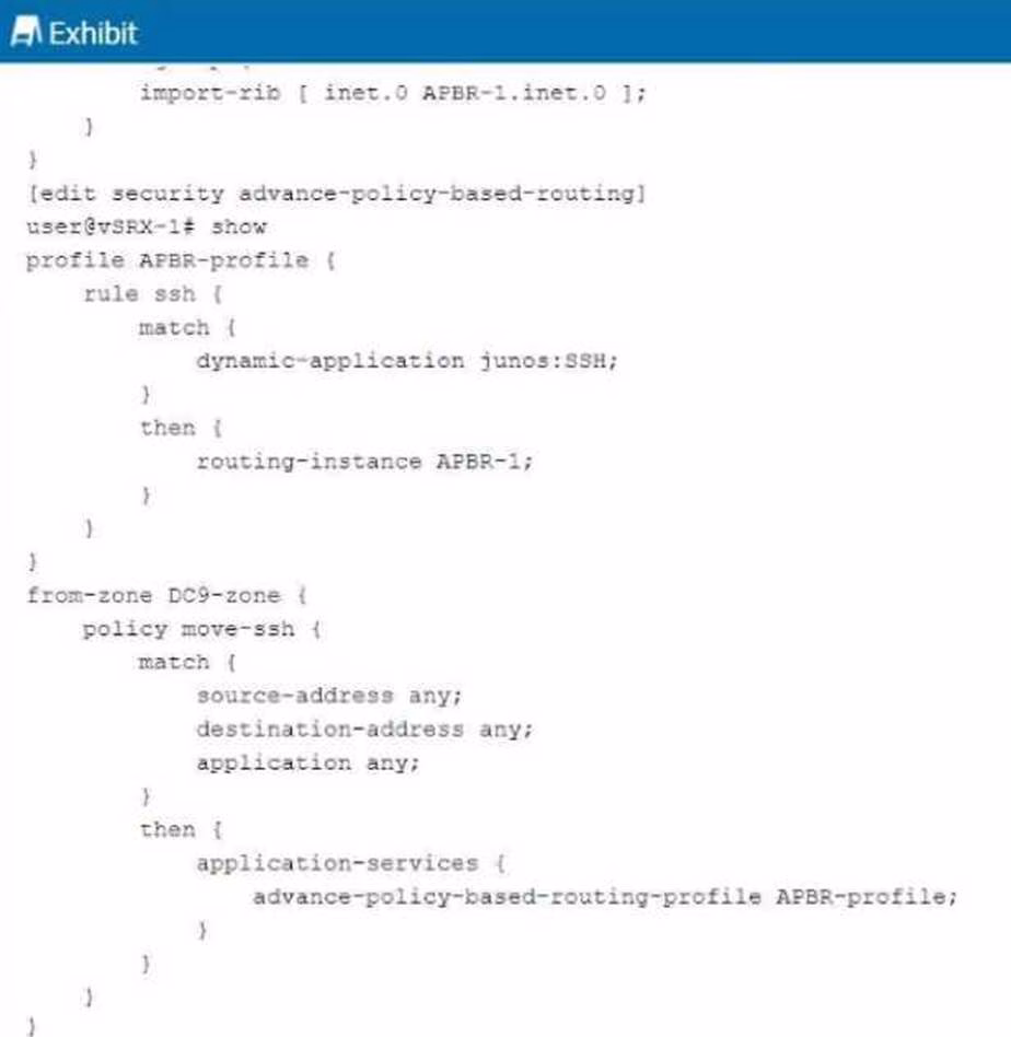

You are having problems configuring advanced policy-based routing.
What should you do to solve the problem?
- A . Apply a policy to the APBR RIB group to only allow the exact routes you need.
- B . Change the routing instance to a forwarding instance.
- C . Change the routing instance to a virtual router instance.
- D . Remove the default static route from the main instance configuration.
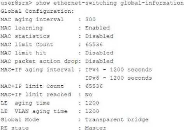
Exhibit:


In which mode is the SRX Series device?
- A . Packet
- B . Ethernet switching
- C . Mixed
- D . Transparent
You configure two Ethernet interfaces on your SRX Series device as Layer 2 interfaces and add them to the same VLAN. The SRX is using the default L2-learning setting. You do not add the interfaces to a security zone.
Which two statements are true in this scenario? (Choose two.)
- A . You are unable to apply stateful security features to traffic that is switched between the two interfaces.
- B . You are able to apply stateful security features to traffic that enters and exits the VLAN.
- C . The interfaces will not forward traffic by default.
- D . You cannot add Layer 2 interfaces to a security zone.
AC
Explanation:
When Ethernet interfaces are configured as Layer 2 and added to the same VLAN without being assigned to a security zone, they will not forward traffic by default. Additionally, because they are operating in a pure Layer 2 switching mode, they lack the capability to enforce stateful security policies. For further details, refer to Juniper Ethernet Switching Layer 2 Documentation.
Explanation of Answer A (Unable to Apply Stateful Security Features):
When two interfaces are configured as Layer 2 interfaces and belong to the same VLAN but are not assigned to any security zone, traffic switched between them is handled purely at Layer 2. Stateful security features, such as firewall policies, are applied at Layer 3, so traffic between these interfaces will not undergo any stateful inspection or firewalling by default. Explanation of Answer C (Interfaces Will Not Forward Traffic):
In Junos, Layer 2 interfaces must be added to a security zone to allow traffic forwarding. Since the interfaces in this scenario are not part of a security zone, they will not forward traffic by default until assigned to a zone. This is a security measure to prevent unintended forwarding of traffic. Juniper Security
Reference: Layer 2 Interface Configuration: Layer 2 interfaces must be properly assigned to security zones to enable traffic forwarding and apply security policies.
Reference: Juniper Networks Layer 2 Interface Documentation.
Which two statements are true about the procedures the Junos security device uses when handling traffic destined for the device itself? (Choose two.)
- A . If the received packet is addressed to the ingress interface, then the device first performs a security policy evaluation for the junos-host zone.
- B . If the received packet is destined for an interface other than the ingress interface, then the device performs a security policy evaluation for the junos-host zone.
- C . If the received packet is addressed to the ingress interface, then the device first examines the host-inbound-traffic configuration for the ingress interface and zone.
- D . If the received packet is destined for an interface other than the ingress interface, then the device performs a security policy evaluation based on the ingress and egress zone.
BC
Explanation:
When handling traffic that is destined for itself, the SRX examines the host-inbound-traffic configuration for the ingress interface and the associated security zone. It evaluates whether the traffic should be allowed based on this configuration. Traffic not addressed to the ingress interface is handled based on security policies within the junos-host zone, which applies to traffic directed to the SRX itself. For more details, refer to Juniper Host Inbound Traffic Documentation.
When handling traffic that is destined for the SRX device itself (also known as host-bound traffic), the SRX follows a specific process to evaluate the traffic and apply the appropriate security policies. The junos-host zone is a special security zone used for managing traffic destined for the device itself, such as management traffic (SSH, SNMP, etc.).
Explanation of Answer B (Packet to a Different Interface):
If the packet is destined for an interface other than the ingress interface, the SRX performs a security policy evaluation specifically for the junos-host zone. This ensures that management or host-bound traffic is evaluated according to the security policies defined for that zone. Explanation of Answer C (Packet to the Ingress Interface):
If the packet is addressed to the ingress interface, the device first checks the host-inbound-traffic configuration for the ingress interface and zone. This configuration determines whether certain types of traffic (such as SSH, HTTP, etc.) are allowed to reach the device on that specific interface.
Step-by-Step Handling of Host-Bound Traffic:
Host-Inbound Traffic: Define which services are allowed to the SRX device itself:
bash
set security zones security-zone <zone-name> host-inbound-traffic system-services ssh
Security Policy for junos-host: Ensure policies are defined for managing traffic destined for the SRX
device:
bash
set security policies from-zone <zone-name> to-zone junos-host policy allow-ssh match source-address any
set security policies from-zone <zone-name> to-zone junos-host policy allow-ssh match destination-address any
Juniper Security
Reference: Junos-Host Zone: This special zone handles traffic destined for the SRX device, including management traffic. Security policies must be configured to allow this traffic.
Reference: Juniper Networks Host-Inbound Traffic Documentation.
Exhibit:
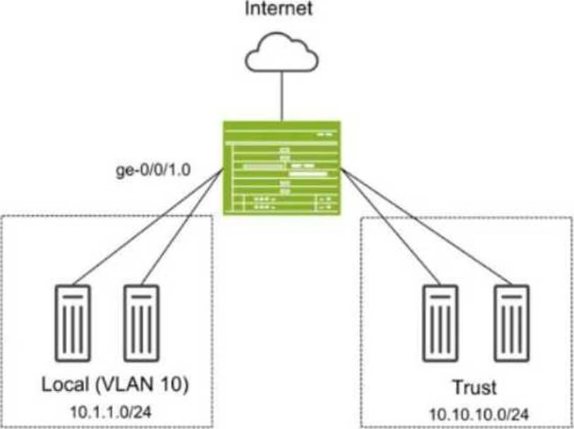

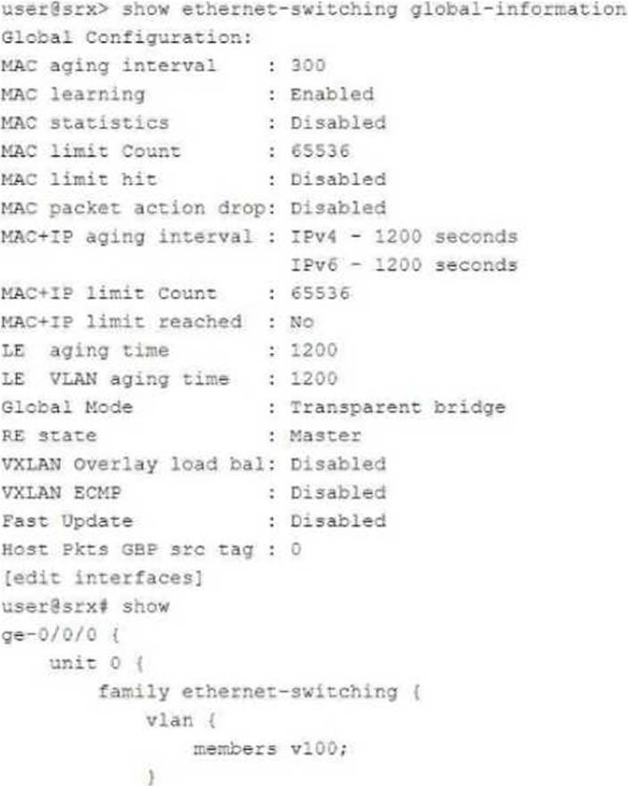
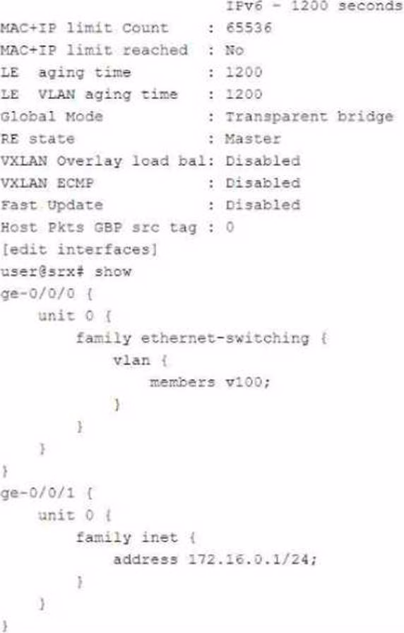
You have deployed an SRX Series device as shown in the exhibit. The devices in the Local zone have recently been added, but their SRX interfaces have not been configured.
You must configure the SRX to meet the following requirements:
Devices in the 10.1.1.0/24 network can communicate with other devices in the same network but not with other networks or the SRX.
You must be able to apply security policies to traffic flows between devices in the Local zone.
Which three configuration elements will be required as part of your configuration? (Choose three.)
- A . set security zones security-zone Local interfaces ge-0/0/1.0
- B . set interfaces ge-0/0/1 unit 0 family ethernet-switching vlan-members 10
- C . set protocols l2-learning global-mode switching
- D . set protocols l2-learning global-mode transparent-bridge
- E . set security zones security-zone Local interfaces irb.10
ABD
Explanation:
In this scenario, we need to configure the SRX Series device so that devices in the Local zone (VLAN 10, 10.1.1.0/24 network) can communicate with each other but not with other networks or the SRX itself. Additionally, you must be able to apply security policies to traffic flows between the devices in the Local zone.
Explanation of Answer A (Assigning Interface to Security Zone):
You need to assign the interface ge-0/0/1.0 to the Local security zone. This is crucial because the SRX only applies security policies to interfaces assigned to security zones. Without this, traffic between devices in the Local zone won’t be processed by security policies. Configuration:
set security zones security-zone Local interfaces ge-0/0/1.0
Explanation of Answer B (Configuring Ethernet-Switching for VLAN 10):
Since we are using Layer 2 switching between devices in VLAN 10, we need to configure the interface to operate in Ethernet switching mode and assign it to VLAN 10. Configuration:
set interfaces ge-0/0/1 unit 0 family ethernet-switching vlan-members 10
Explanation of Answer D (Transparent Bridging Mode for Layer 2):
The global mode for Layer 2 switching on the SRX device must be set to transparent-bridge. This
ensures that the SRX operates in Layer 2 mode and can switch traffic between devices without
routing.
Configuration:
set protocols l2-learning global-mode transparent-bridge
Summary:
Interface Assignment: Interface ge-0/0/1.0 is assigned to the Local zone to allow policy enforcement.
Ethernet-Switching: The interface is configured for Layer 2 Ethernet switching in VLAN 10. Transparent Bridging: The SRX is configured in Layer 2 transparent-bridge mode for switching between devices.
Juniper Security
Reference: Layer 2 Bridging and Switching Overview: This mode allows the SRX to act as a Layer 2 switch for forwarding traffic between VLAN members without routing.
Reference: Juniper Transparent Bridging Documentation.
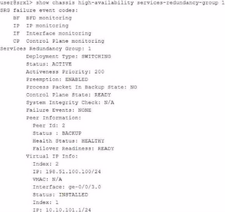
Exhibit:
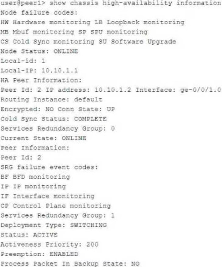


Referring to the exhibit, which statement is true?
- A . SRG1 is configured in hybrid mode.
- B . The ICL is encrypted.
- C . If SRG1 moves to peer 2, peer 1 will drop packets sent to the SRG1 interfaces.
- D . If SRG1 moves to peer 2, peer 1 will forward packets sent to the SRG1 interfaces.
D
Explanation:
The exhibit describes a Chassis Cluster configuration with high availability (HA) settings. The key information is related to Service Redundancy Group 1 (SRG1) and its failover behavior between the two peers.
Explanation of Answer D (Packet Forwarding after Failover):
In a typical SRX HA setup with active/backup configuration, if the SRG1 group moves to peer 2 (the backup), peer 1 (previously the active node) will forward packets to peer 2 instead of dropping them. This ensures smooth failover and seamless continuation of services without packet loss.
This behavior is part of the active/backup failover process in SRX chassis clusters, where the standby peer takes over traffic processing without disruption. Juniper Security
Reference: Chassis Cluster Failover Behavior: When a service redundancy group fails over to the backup peer, the previously active peer forwards traffic to the new active node.
Reference: Juniper Chassis Cluster Documentation.
You are asked to create multiple virtual routers using a single SRX Series device. You must ensure that each virtual router maintains a unique copy of the routing protocol daemon (RPD) process.
Which solution will accomplish this task?
- A . Secure wire
- B . Tenant system
- C . Transparent mode
- D . Logical system
D
Explanation:
Logical systems on SRX Series devices allow the creation of separate virtual routers, each with its unique RPD process. This segmentation ensures that routing and security policies are isolated across different logical systems, effectively acting like independent routers within a single SRX device.
For further information, see Juniper Logical Systems Documentation.
To create multiple virtual routers on a single SRX Series device, each with its own unique copy of the routing protocol daemon (RPD) process, you need to use logical systems. Logical systems allow for the segmentation of an SRX device into multiple virtual routers, each with independent configurations, including routing instances, policies, and protocol daemons. Explanation of Answer D (Logical System):
A logical system on an SRX device enables you to create multiple virtual instances of the SRX, each operating independently with its own control plane and routing processes. Each logical system gets a separate copy of the RPD process, ensuring complete isolation between virtual routers.
This is the correct solution when you need separate routing instances with their own RPD processes on the same physical device.
Configuration Example:
bash
set logical-systems <logical-system-name> interfaces ge-0/0/0 unit 0
set logical-systems <logical-system-name> routing-options static route 0.0.0.0/0 next-hop 192.168.1.1
Juniper Security
Reference: Logical Systems Overview: Logical systems allow for the creation of multiple virtual instances within a single SRX device, each with its own configuration and control plane.
Reference: Juniper Logical Systems Documentation.
Click the Exhibit button.

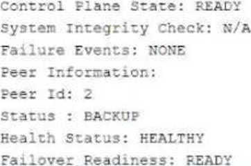
Referring to the exhibit, which three actions do you need to take to isolate the hosts at the switch port level if they become infected with malware? (Choose three.)
- A . Enroll the SRX Series device with Juniper ATP Cloud.
- B . Use a third-party connector.
- C . Deploy Security Director with Policy Enforcer.
- D . Configure AppTrack on the SRX Series device.
- E . Deploy Juniper Secure Analytics.
ABC
Explanation:
You want to deploy two vSRX instances in different public cloud providers to provide redundant security services for your network. Layer 2 connectivity between the two vSRX instances is not possible.
What would you configure on the vSRX instances to accomplish this task?
- A . Chassis cluster
- B . Secure wire
- C . Multinode HA
- D . Virtual chassis
You are asked to connect two hosts that are directly connected to an SRX Series device. The traffic should flow unchanged as it passes through the SRX, and routing or switch lookups should not be performed. However, the traffic should still be subjected to security policy checks.
What will provide this functionality?
- A . MACsec
- B . Mixed mode
- C . Secure wire
- D . Transparent mode
C
Explanation:
Secure wire mode on SRX devices allows traffic to flow transparently through the firewall without being routed or switched, while still applying security policies. This is ideal for scenarios where traffic inspection is required without altering the traffic path or performing additional routing decisions. For further details on Secure Wire, refer to Juniper Secure Wire Documentation.
In this scenario, you want traffic to pass through the SRX unchanged (without routing or switching lookups) but still be subject to security policy checks. The best solution for this requirement is Secure
Wire.
Explanation of Answer C (Secure Wire):
Secure Wire allows traffic to flow through the SRX without any Layer 3 routing or Layer 2 switching decisions. It effectively bridges two interfaces at Layer 2 while still applying security policies. This ensures that traffic remains unchanged, while security policies (such as firewall rules) can still be enforced.
This is an ideal solution when you need the SRX to act as a "bump in the wire" for security enforcement without changing the traffic or performing complex network lookups. Juniper Security
Reference: Secure Wire Functionality: Provides transparent Layer 2 forwarding with security policy enforcement, making it perfect for scenarios where traffic needs to pass through unchanged.
Reference: Juniper Secure Wire Documentation.
Which two statements are true when setting up an SRX Series device to operate in mixed mode? (Choose two.)
- A . A physical interface can be configured to be both a Layer 2 and a Layer 3 interface at the same time.
- B . User logical systems support Layer 2 traffic processing.
- C . The SRX must be rebooted after configuring at least one Layer 3 and one Layer 2 interface.
- D . Packets from Layer 2 interfaces are switched within the same bridge domain.
CD
Explanation:
In mixed mode, SRX devices can simultaneously handle Layer 2 switching and Layer 3 routing, but a reboot is required when configuring Layer 2 and Layer 3 interfaces to ensure the configuration takes effect. Layer 2 packets are switched within the defined bridge domain. Further guidance on SRX mixed mode can be found at Juniper Mixed Mode Documentation.
When an SRX Series device is configured in mixed mode, both Layer 2 switching and Layer 3 routing functionalities can be used on the same device. This enables the SRX to act as both a router and a switch for different interfaces. However, there are certain considerations:
Explanation of Answer C (Reboot Requirement):
After configuring the SRX to operate with at least one Layer 2 interface and one Layer 3 interface, the device needs to be rebooted. This is required to properly initialize the mixed mode configuration, as the SRX needs to switch between Layer 2 and Layer 3 processing modes.
Explanation of Answer D (Layer 2 Traffic Handling):
In mixed mode, traffic from Layer 2 interfaces is switched within the same bridge domain. A bridge
domain defines a Layer 2 broadcast domain, and packets from Layer 2 interfaces are forwarded based
on MAC addresses within that domain.
Juniper Security
Reference: Mixed Mode Overview: Juniper SRX devices can operate in mixed mode to handle both Layer 2 and Layer 3 traffic simultaneously.
Reference: Juniper Mixed Mode Documentation.
You have configured the backup signal route IP for your multinode HA deployment, and the ICL link fails.
Which two statements are correct in this scenario? (Choose two.)
- A . The current active node retains the active role.
- B . The active node removes the active signal route.
- C . The backup node changes the routing preference to the other node at its medium priority.
- D . The active node keeps the active signal route.
Exhibit:

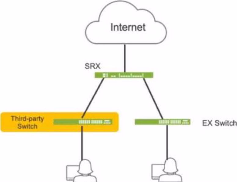
Host A shown in the exhibit is attempting to reach the Web1 webserver, but the connection is failing. Troubleshooting reveals that when Host A attempts to resolve the domain name of the server (web.acme.com), the request is resolved to the private address of the server rather than its public IP.
Which feature would you configure on the SRX Series device to solve this issue?
- A . Persistent NAT
- B . Double NAT
- C . DNS doctoring
- D . STUN protocol
C
Explanation:
DNS doctoring modifies DNS responses for hosts behind NAT devices, allowing them to receive the correct public IP address for internal resources when queried from the public network. This prevents issues where private IPs are returned and are not reachable externally. For details, visit Juniper DNS Doctoring Documentation.
In this scenario, Host A is trying to resolve the domain name web.acme.com, but the DNS resolution returns the private IP address of the web server instead of its public IP. This is a common issue in networks where private addresses are used internally, but public addresses are required for external clients.
Explanation of Answer C (DNS Doctoring):
DNS doctoring is a feature that modifies DNS replies as they pass through the SRX device. In this case, DNS doctoring can be used to replace the private IP address returned in the DNS response with the correct public IP address for Host A. This allows external clients to reach internal resources without being aware of their private IP addresses.
Configuration Example:
bash
set security nat dns-doctoring from-zone untrust to-zone trust
Juniper Security
Reference: DNS Doctoring Overview: DNS doctoring is used to modify DNS responses so that external clients can
access internal resources using public IP addresses.
Reference: Juniper DNS Doctoring Documentation.
Exhibit:

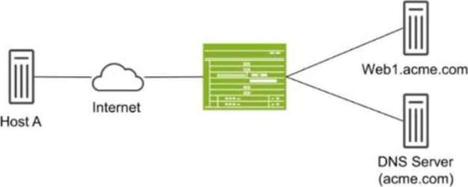
Referring to the exhibit, what do you use to dynamically secure traffic between the Azure and AWS clouds?
- A . You can dynamically secure traffic between the clouds by using user identities in the security policies.
- B . You can dynamically secure traffic between the clouds by using advanced connection tracking in the security policies.
- C . You can dynamically secure traffic between the clouds by using security tags in the security policies.
- D . You can dynamically secure traffic between the clouds by using URL filtering in the security policies.
C
Explanation:
Security tags facilitate dynamic traffic management between cloud environments like Azure and AWS. Tags allow flexible policies that respond to cloud-native events or resource changes, ensuring secure inter-cloud communication. For more information, see Juniper Cloud Security Tags.
In the scenario depicted in the exhibit, where traffic needs to be dynamically secured between Azure and AWS clouds, the best method to achieve dynamic security is by using security tags in the security policies.
Explanation of Answer C (Security Tags in Security Policies):
Security tags allow dynamic enforcement of security policies based on metadata rather than static IP addresses or zones. This is crucial in cloud environments, where resources and IP addresses can change dynamically.
Using security tags in the security policies, you can associate traffic flows with specific applications, services, or virtual machines, regardless of their underlying IP addresses or network locations. This ensures that security policies are automatically updated as cloud resources change. Juniper Security
Reference: Dynamic Security with Security Tags: This feature allows you to dynamically secure cloud-based traffic using metadata and tags, ensuring that security policies remain effective even in dynamic environments.
Reference: Juniper Security Tags Documentation.
Exhibit:
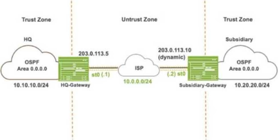

Referring to the exhibit, which IKE mode will be configured on the HQ-Gateway and Subsidiary-Gateway?
- A . Main mode on both the gateways
- B . Aggressive mode on both the gateways
- C . Main mode on the HQ-Gateway and aggressive mode on the Subsidiary-Gateway
- D . Aggressive mode on the HQ-Gateway and main mode on the Subsidiary-Gateway
You are deploying threat remediation to endpoints connected through third-party devices.
In this scenario, which three statements are correct? (Choose three.)
- A . All third-party switches must support AAA/RADIUS and Dynamic Authorization Extensions to the RADIUS protocol.
- B . The connector uses an API to gather endpoint MAC address information from the RADIUS server.
- C . All third-party switches in the specified network are automatically mapped and registered with the RADIUS server.
- D . The connector queries the RADIUS server for the infected host endpoint details and initiates a change of authorization (CoA) for the infected host.
- E . The RADIUS server sends Status-Server messages to update infected host information to the connector.
ABD
Explanation:
For threat remediation in a third-party network, the RADIUS protocol is necessary to communicate with the RADIUS server for details about infected hosts. CoA enables security measures to be enforced based on endpoint information provided by the RADIUS server. Details on this setup can be found in Juniper RADIUS and AAA Documentation.
When deploying threat remediation to endpoints connected through third-party devices, such as switches, the following conditions must be met for proper integration and functioning: Explanation of Answer A (Support for AAA/RADIUS and Dynamic Authorization Extensions): Third-party switches must support AAA (Authentication, Authorization, and Accounting) and RADIUS with Dynamic Authorization Extensions. These extensions allow dynamic updates to be made to a session’s authorization parameters, which are essential for enforcing access control based on threat detection.
Explanation of Answer B (Connector Gathers MAC Information via API):
The connector uses an API to gather MAC address information from the RADIUS server. This MAC address data is necessary to identify and take action on infected hosts or endpoints. Explanation of Answer D (Connector Initiates CoA):
The connector queries the RADIUS server for infected host details and triggers a Change of Authorization (CoA) for the infected host. The CoA allows the connector to dynamically alter the host’s access permissions or isolate the infected host based on its threat status. Juniper Security
Reference: Threat Remediation via RADIUS: Dynamic remediation actions, such as CoA, can be taken based on information received from the RADIUS server regarding infected hosts.
Reference: Juniper RADIUS and CoA Documentation.
Exhibit:

Referring to the exhibit, which two statements are correct? (Choose two.)
- A . You cannot secure intra-VLAN traffic with a security policy on this device.
- B . You can secure inter-VLAN traffic with a security policy on this device.
- C . The device can pass Layer 2 and Layer 3 traffic at the same time.
- D . The device cannot pass Layer 2 and Layer 3 traffic at the same time.
BC
Explanation:
The exhibit provides information about an SRX Series device operating in transparent mode (Layer 2)
and Layer 3 routing at the same time. Let’s break down the correct answers:
Explanation of Answer B (Secure Inter-VLAN Traffic with a Security Policy):
The SRX device can secure inter-VLAN traffic because it supports security policies for Layer 3 traffic between different VLANs. In this case, traffic moving between different VLANs (i.e., Layer 3 traffic) can be processed and controlled using security policies.
Explanation of Answer C (Pass Layer 2 and Layer 3 Traffic Simultaneously):
The SRX device can handle both Layer 2 and Layer 3 traffic simultaneously. In mixed mode, the device is capable of switching traffic at Layer 2 (intra-VLAN) while also routing traffic at Layer 3 (inter-VLAN). This is evident from the global configuration showing transparent bridge mode and Layer 3 interfaces.
Juniper Security
Reference: Mixed Mode Overview: Juniper SRX devices in mixed mode can operate as both a Layer 2 switch and a Layer 3 router, allowing it to pass traffic at both layers simultaneously.
Reference: Juniper Mixed Mode Documentation.
You want to test how the device handles a theoretical session without generating traffic on the Junos security device.
Which command is used in this scenario?
- A . request security policies check
- B . show security flow session
- C . show security match-policies
- D . show security policies
A
Explanation:
The request security policies check command allows you to simulate a session through the SRX device, checking the security policy action that would apply without needing to send real traffic. This helps in validating configurations before actual deployment. For more details, see Juniper Security Policies Testing.
The command request security policies check is used to test how a Junos security device handles a theoretical session without generating actual traffic. This command is useful for validating how security policies would be applied to a session based on various parameters like source and destination addresses, application type, and more. Explanation of Answer A (request security policies check):
This command allows you to simulate a session and verify which security policies would be applied
to the session. It’s a proactive method to test security policy configurations without the need to
generate real traffic.
Example usage:
bash
request security policies check from-zone trust to-zone untrust source 10.1.1.1 destination 192.168.1.1 protocol tcp application junos-https Juniper Security
Reference: Security Policies Check: This command provides a way to simulate and verify security policy behavior without actual traffic.
Reference: Juniper Security Policy Documentation.
Exhibit:

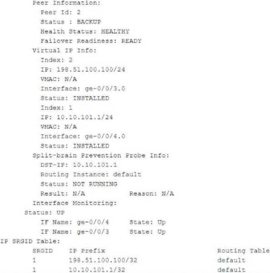

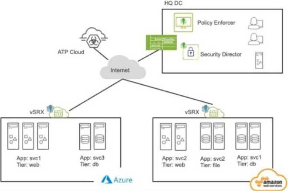
Referring to the exhibit, which two statements are correct? (Choose two.)
- A . The ge-0/0/3.0 and ge-0/0/4.0 interfaces are not active and will not respond to ARP requests to the virtual IP MAC address.
- B . This device is the backup node for SRG1.
- C . The ge-0/0/3.0 and ge-0/0/4.0 interfaces are active and will respond to ARP requests to the virtual IP MAC address.
- D . This device is the active node for SRG1.
AB
Explanation:
The interfaces are active and respond to ARP for virtual IP as long as the node is the primary or active node in the SRG group. This ensures high availability and proper traffic forwarding. For information, refer to Juniper SRX HA Documentation.
The exhibit shows information about a chassis cluster and its services redundancy group (SRG1). Let’s analyze the relevant details:
Explanation of Answer B (Backup Node for SRG1):
The exhibit indicates that this SRX device is in the backup role for SRG1. The status: BACKUP field confirms that this device is currently in a standby role and is not the active node for the services redundancy group.
Explanation of Answer A (Interfaces Not Active):
Since the device is in the backup role, the interfaces ge-0/0/3.0 and ge-0/0/4.0 will not respond to ARP requests for the virtual IP’s MAC address. Only the active node’s interfaces respond to ARP requests in a chassis cluster configuration.
Juniper Security
Reference: Chassis Cluster Redundancy Overview: In a chassis cluster, the backup node does not respond to ARP requests for the virtual IP. Only the active node handles such requests to ensure seamless traffic forwarding.
Reference: Juniper Chassis Cluster Documentation.
Which role does an SRX Series device play in a DS-Lite deployment?
- A . Softwire concentrator
- B . STUN server
- C . STUN client
- D . Softwire initiator
Which two statements are correct about the ICL in an active/active mode multinode HA environment? (Choose two.)
- A . The ICL is strictly a Layer 2 interface.
- B . The ICL uses a separate routing instance to communicate with remote multinode HA peers.
- C . The ICL traffic can be encrypted.
- D . The ICL is the local device management interface in a multinode HA environment.
Exhibit:


Your company uses SRX Series devices to establish an IPsec VPN that connects Site-1 and the HQ networks. You want VoIP traffic to receive priority over data traffic when it is forwarded across the VPN.
Which three actions should you perform in this scenario? (Choose three.)
- A . Enable next-hop tunnel binding.
- B . Create a firewall filter that identifies VoIP traffic and associates it with the correct forwarding class.
- C . Configure CoS forwarding classes and scheduling parameters.
- D . Enable the copy-outer-dscp parameter so that DSCP header values are copied to the tunneled packets.
- E . Enable the multi-sa parameter to enable two separate IPsec SAs for the VoIP and data traffic.
Your IPsec tunnel is configured with multiple security associations (SAs). Your SRX Series device supports the CoS-based IPsec VPNs with multiple IPsec SAs feature. You are asked to configure CoS for this tunnel.
Which two statements are true in this scenario? (Choose two.)
- A . The local and remote gateways do not need the forwarding classes to be defined in the same order.
- B . A maximum of four forwarding classes can be configured for a VPN with the multi-sa forwarding-classes statement.
- C . The local and remote gateways must have the forwarding classes defined in the same order.
- D . A maximum of eight forwarding classes can be configured for a VPN with the multi-sa forwarding-classes statement.
The exhibit shows part of the flow session logs.
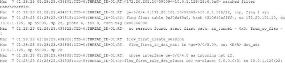

Which two statements are true in this scenario? (Choose two.)
- A . The existing session is found in the table, and the fast path process begins.
- B . This packet arrives on interface ge-0/0/4.0.
- C . Junos captures a TCP packet from source address 172.20.101.10 destined to 10.0.1.129.
- D . Destination NAT occurs.
You have deployed automated threat mitigation using Security Director with Policy Enforcer, Juniper ATP Cloud, SRX Series devices, Forescout, and third-party switches.
In this scenario, which device is responsible for communicating directly to the third-party switches when infected hosts need to be blocked?
- A . Forescout
- B . Policy Enforcer
- C . Juniper ATP Cloud
- D . SRX Series device
B
Explanation:
Policy Enforcer receives these policies and translates them into device-specific commands. It then communicates with the third-party switches (using protocols like SNMP, RADIUS, or vendor-specific APIs) to enforce those commands, such as blocking the infected hosts’ MAC addresses or port access.
Why Policy Enforcer is the Right Choice:
Centralized Enforcement: Policy Enforcer acts as the central point of enforcement for Security Director policies, ensuring consistent security across the network.
Multi-Vendor Support: It can interact with a wide range of network devices, including switches from different vendors.
Automation: Policy Enforcer automates the policy enforcement process, enabling rapid response to threats.
Reference: Forescout and Juniper integration for network access control .
Referring to the exhibit,
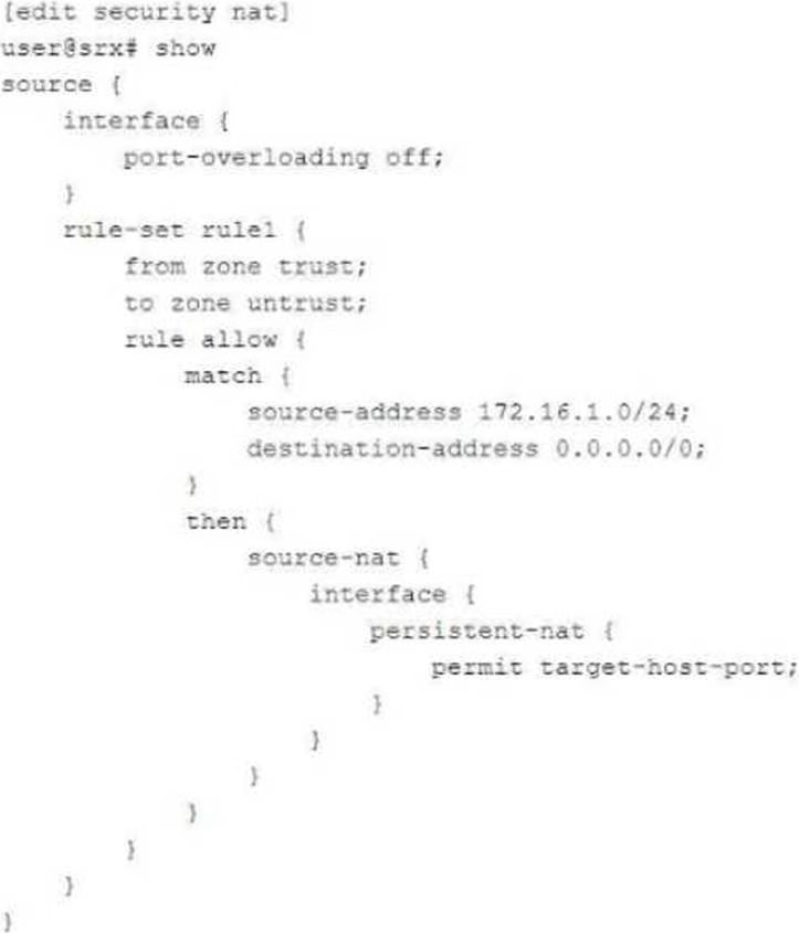

Which two statements are correct about the NAT configuration? (Choose two.)
- A . Both the internal and the external host can initiate a session after the initial translation.
- B . Only a specific host can initiate a session to the reflexive address after the initial session.
- C . Any external host will be able to initiate a session to the reflexive address.
- D . The original destination port is used for the source port for the session.
BD
Explanation:
Persistent NAT with target-host restricts session initiation to specific addresses, enhancing security. Reflexive NAT supports multiple connections by preserving the original port. Refer to Juniper NAT Configuration Documentation.
Referring to the NAT configuration shown in the exhibit:
Specific Host Can Initiate a Session (Answer B): The configuration uses persistent NAT with the permit target-host-port statement. This allows a specific external host (based on the target host and port used in the initial session) to initiate a session back to the internal host after the initial session has been established.
Persistent NAT ensures that the translation state is maintained, allowing external hosts to connect back only under specific conditions (e.g., the same target host and port as used in the original connection).
Original Destination Port (Answer D): The original destination port used by the internal host is retained as the source port when the session is established from outside to inside. This behavior is a result of how persistent NAT binds the internal and external sessions, ensuring that communication occurs over the same port used for the initial session.
Reference: Juniper NAT and Persistent NAT configuration documentation.
You are using ADVPN to deploy a hub-and-spoke VPN to connect your enterprise sites.
Which two statements are true in this scenario? (Choose two.)
- A . ADVPN creates a full-mesh topology.
- B . IBGP routing is required.
- C . OSPF routing is required.
- D . Certificate-based authentication is required.
You want to create a connection for communication between tenant systems without using physical revenue ports on the SRX Series device.
What are two ways to accomplish this task? (Choose two.)
- A . Use an external router.
- B . Use an interconnect VPLS switch.
- C . Use a secure wire.
- D . Use a point-to-point logical tunnel.
An ADVPN configuration has been verified on both the hub and spoke devices and it seems fine.
However, OSPF is not functioning as expected.
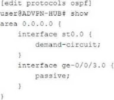

Referring to the exhibit, which two statements under interface st0.0 on both the hub and spoke devices would solve this problem? (Choose two.)
- A . interface-type p2mp
- B . dynamic-neighbors
- C . passive
- D . interface-type p2p
AB
Explanation:
For ADVPN with OSPF, using a point-to-multipoint (p2mp) interface type and enabling dynamic-neighbors are crucial. This configuration allows dynamic discovery of neighbors and the establishment of tunnels. For more information, refer to Juniper ADVPN Configuration Guide.
In the ADVPN configuration, OSPF isn’t functioning as expected due to the interface configuration on st0.0. Here are the adjustments needed:
Interface Type p2mp (Answer A): OSPF requires that the tunnel interface be set to p2mp (point-to-multipoint) to allow OSPF to communicate with multiple dynamic neighbors over the ADVPN tunnels.
Command Example:
bash
set interfaces st0.0 family inet ospf interface-type p2mp
Dynamic Neighbors (Answer B): The dynamic neighbors statement allows OSPF to discover and communicate with dynamically established spokes in an ADVPN environment. This is essential for ADVPN to function properly since the tunnel endpoints are not static.
Command Example:
bash
set protocols ospf area 0.0.0.0 interface st0.0 dynamic-neighbors
These settings ensure OSPF properly functions over dynamically created ADVPN tunnels.
Reference: Juniper ADVPN and OSPF configuration .
You have deployed an SRX Series device at your network edge to secure Internet-bound sessions for your local hosts using source NAT. You want to ensure that your users are able to interact with applications on the Internet that require more than one TCP session for the same application session.
Which two features would satisfy this requirement? (Choose two.)
- A . address persistence
- B . STUN
- C . persistent NAT
- D . double NAT
AC
Explanation:
Address persistence ensures that the same NAT IP address is used for all sessions originating from a single source IP. Persistent NAT maintains connections for applications needing multiple sessions, like VoIP. Additional details are available in Juniper NAT Documentation.
For applications that require multiple TCP sessions for the same application session (such as VoIP or certain online games), the SRX device needs to handle NAT properly to maintain session continuity. Here’s what helps:
Address Persistence (Answer A): Address persistence ensures that multiple sessions initiated by the same internal host are mapped to the same external IP address. This is crucial for applications that use multiple TCP sessions to maintain a stateful connection with the external server.
Command Example:
bash
set security nat source persistent-nat address-persistence
Persistent NAT (Answer C): This feature allows the external server to initiate new connections to the
internal client using the same NAT translation. It’s essential for applications that require consistent
NAT mappings across multiple sessions.
Command Example:
bash
set security nat source persistent-nat permit target-host-port
These features ensure that applications with multiple TCP sessions work seamlessly across NAT.
Reference: Juniper NAT and persistent NAT documentation.
Referring to the exhibit,
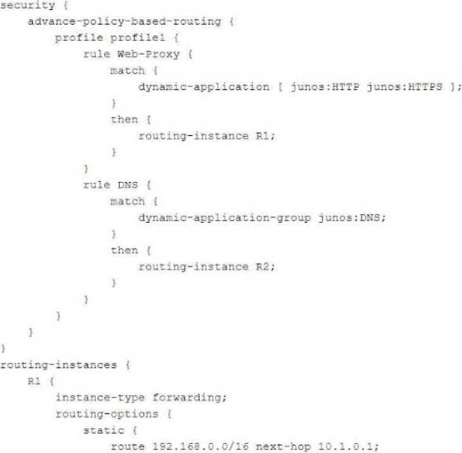

Which statement about TLS 1.2 traffic is correct?
- A . TLS 1.2 traffic will be sent to routing instance R1 but not forwarded to the next hop.
- B . TLS 1.2 traffic will be sent to routing instance R1 and forwarded to next hop 10.1.0.1.
- C . TLS 1.2 traffic will be sent to routing instance R2 but not forwarded to the next hop.
- D . TLS 1.2 traffic will be sent to routing instance R2 and forwarded to next hop 10.2.0.1.
You have an initial setup of ADVPN with two spokes and a hub. A host at partner Spoke-1 is sending traffic to a host at partner Spoke-2.
In this scenario, which statement is true?
- A . Spoke-1 will establish a VPN to Spoke-2 when this is first deployed, so traffic will be sent immediately to Spoke-2.
- B . Spoke-1 will send the traffic through the hub and not use a direct VPN to Spoke-2.
- C . Spoke-1 will establish the tunnel to Spoke-2 before sending any of the host traffic.
- D . Spoke-1 will send the traffic destined to Spoke-2 through the hub until the VPN is established between the spokes.
Referring to the exhibit,
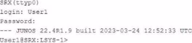

which two statements about User1 are true? (Choose two.)
- A . User1 has access to the configuration specific to their assigned logical system.
- B . User1 is logged in to logical system LSYS-1.
- C . User1 can add logical units to an interface that a primary administrator has not previously assigned.
- D . User1 can view outputs from other user logical systems.
AB
Explanation:
In this configuration, User1 is logged into logical system LSYS-1, which restricts access and visibility to that particular system. This ensures isolation between logical systems on the same physical device. Only a system administrator can assign additional permissions. For more details, see Juniper Logical Systems Guide.
From the exhibit, we see that User1 is logged into logical system LSYS-1:
Access to Assigned Logical System (Answer A): User1, being logged into the logical system LSYS-1, only has access to the configuration and interfaces within that logical system. This is a key feature of logical systems in Junos, ensuring users are restricted to their respective environments.
Logged into LSYS-1 (Answer B): The prompt shows that User1 is currently operating in LSYS-1, as indicated by the User1@SRX:LSYS-1> command line.
Reference: Juniper logical systems configuration and user permissions.
Exhibit:
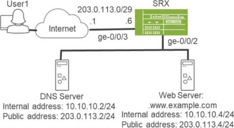

You are asked to ensure that Internet users can access the company’s internal webserver using its FQDN. However, the internal DNS server’s A record only points to the webserver’s private address.
Referring to the exhibit, which two actions are required to complete this task? (Choose two.)
- A . Disable the DNS ALG.
- B . Configure static NAT for both the DNS server and the webserver.
- C . Configure destination NAT for both the DNS server and the webserver.
- D . Configure proxy ARP on ge-0/0/3.
BD
Explanation:
In the scenario where internal users are trying to access the company’s web server via its FQDN but the DNS server resolves to a private IP, two key actions are needed:
Static NAT (Answer B): Since the internal DNS server resolves the web server to its private IP address (10.10.10.4/24), you need to configure static NAT for both the DNS server and the webserver. This will ensure that requests coming from the internet will be translated to the web server’s public IP (203.0.113.4) and the DNS server’s public IP (203.0.113.2). Example Command:
bash
set security nat static rule-set public-to-private from zone untrust
set security nat static rule-set public-to-private rule dns-server match destination-address 203.0.113.2/32
set security nat static rule-set public-to-private rule dns-server then static-nat-prefix 10.10.10.2/32 set security nat static rule-set public-to-private rule web-server match destination-address 203.0.113.4/32
set security nat static rule-set public-to-private rule web-server then static-nat-prefix 10.10.10.4/32
Proxy ARP (Answer D): The SRX needs to respond to ARP requests for the public IP addresses of both
the DNS and webserver on the interface facing the internet (ge-0/0/3). This allows the SRX to handle
requests directed at the public IPs.
Example Command:
set interfaces ge-0/0/3 unit 0 family inet proxy-arp interface-address 203.0.113.2/32 set interfaces ge-0/0/3 unit 0 family inet proxy-arp interface-address 203.0.113.4/32
These two configurations allow external users to access the internal web server via its public IP, as resolved by the DNS server.
Reference: Juniper NAT and proxy ARP documentation .