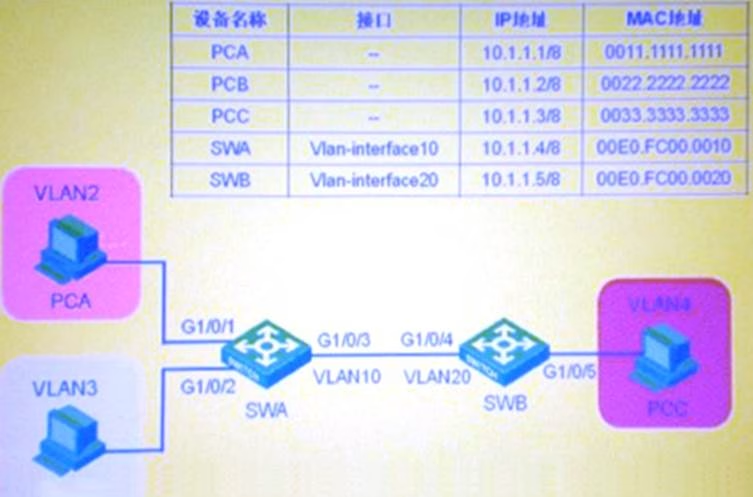
In the switching network shown in the figure, VLAN10 is set as Isolate-user-vlan on switch SWA, VLAN2 and VLAN3 are set as Secondary VLAN of VLAN 10; VLAN2 and VLAN20 are created on switch SWB, and VLAN20 is set as Isolate-user-vlan, and VLAN4 is set as Secondary VLAN of VLAN20. After setting the IP addresses of each device as shown in the figure, which of the following statement is correct?
In the switching network shown in the figure, VLAN10 is set as Isolate-user-vlan on switch SWA, VLAN2 and VLAN3 are set as Secondary VLAN of VLAN 10; VLAN2 and VLAN20 are created on switch SWB, and VLAN20 is set as Isolate-user-vlan, and VLAN4 is set as Secondary VLAN of VLAN20. After setting the IP addresses of each device as shown in the figure, which of the following statement is correct?

A . PCA’s message enters from SWA’s GigabitEthe1/0/1 port and comes out from GigabitEthem1/0/3 port with the VLAN tag VLAN10.
B . PCA’s message comes out of SWA’s GigabitEthem1/0/3 port and enters SWB’s GigabitEthem1/0/4 port without a VLAN Tag.
C . When SWB accesses PCA, the VLAN tag of the message coming out of SWB’s GigabitEthem1/0/4 port is VLAN20.
D . SWB’s message does not carry VLAN after it comes out of SWA’s GigabitEthernet1/0/3 from GigabitEthem1/0/1 port
Answer: D
Latest GB0-372-ENU Dumps Valid Version with 432 Q&As
Latest And Valid Q&A | Instant Download | Once Fail, Full Refund

