H3C GB0-372-ENU H3CSE-RS-SW Online Training
H3C GB0-372-ENU Online Training
The questions for GB0-372-ENU were last updated at Feb 19,2025.
- Exam Code: GB0-372-ENU
- Exam Name: H3CSE-RS-SW
- Certification Provider: H3C
- Latest update: Feb 19,2025
Switches SWA and SWB are connected together through two optical fiber Gigabit Ethernet links, and the following interface configuration is available on switch SWA:
[SWA] interface GigabitEthernet 1/0/1
[SWA-GigabitEthernet 1/0/1] gvrp
[SWA-GigabitEthernet 1/0/1] port link-type trunk
[SWA-GigabitEthernet 1/0/1] port trunk permit vlan 1 10
[SWA] interface GigabitEthernet 1/0/2
[SWA-GigabitEthernet 1/0/2] port link-type trunk
[SWA-GigabitEthernet 1/0/2] port trunk permit vlan 1 10
From the above, we can know which of the following?
- A . GigabitEthernet1/0/1 and GigabitEthe1/0/2 cannot be added to the same aggregation group
- B . Only when the configuration of GigabitEthe1/0/2 is changed to be consistent with that of GigabitEthe1/0/1, can the two be added to the same aggregation group.
- C . If MSTP is enabled on the SWA4 switch, one of GigabitEthernet 1/0/1 and GigabitEthernet 1/0/2 will be blocked.
- D . If the SWA switch has MSTP enabled, GigabitEthe1/0/1 and GigabitEthe1/0/2 can participate in forwarding
The IP address of host PCA is 40.1.1.1, and the MAC address is 0011.1111.1111. PCA is connected to the GigabitEthernet1/0/1 port of switch SWA. The following commands are configured on switch SWA:
[SWA] vlan 10
[SWA-vlan10] quit
[SWA] vlan 20
[SWA-vlan20] protocol-vlan ipv4
[SWA-vlan20] quit
[SWA] vlan 30
[SWA-vlan30] quit
[SWA] mac-vlan mac-address 0011 1111-1111 vlan 30
[SWA] vlan 40
[SWA-vlan40] ip-subnet-vlan ip 40.1.1.0 255.255.255.0
[SWA-vlan40] quit
[SWA] interface GigabitEthernet 1/0/1
[SWA-GigabitEthernet1/0/1] port link-type hybrid
[SWA-GigabitEthernet1/0/1] port hybrid pvid vlan 10
[SWA-GigabitEthernet1/0/1] port hybrid vlan 10 20 30 40 untagged
[SWA-GigabitEthernet1/0/1] port hybrid protocol-vlan vlan 20 0
[SWA-GigabitEthernet1/0/1] port hybrid ip-subnet-vlan vlan 40
[SWA-GigabitEthernet1/0/1] mac-vlan enable
After the configuration is complete, which of the following can be determined that PCA will join?
- A . VLAN 10
- B . VLAN 20
- C . VLAN 30
- D . VLAN 40
- E . The configuration command is incorrect
The customer’s six switches SWA, SWB, SWC, SWD, SWE, and SWF are connected together through a LAN to form an RRPP ring. The RRPP status is checked on SWB as follows:
<SWB>dis rrpp verbose domain 1 Domain ID: 1
Ring ID: 1 Ring Level: 0
Node Mode: Transit Ring state: –
Enable Status: YesActive Status: Yes
Primary port: GigabitEthernet2/0/1 Port status: UP Secondary port: GigabitEthernet2/0/2 Port status: UP Ring ID :2
Ring Level: 1 Node Mode: Edge Ring state: –
Enable Status: YesActive Status: Yes
Common port: GigabitEthernet2/0/1 Port status: UP GigabitEthernet2/0/2 Port status: UP
Edge port: GigabitEthernet2/0/3 Port status: UP Ring ID: 3
Ring Level: 1
Node Mode: Edge Ring state: –
Enable Status: YesActive Status: Yes
Common port: GigabitEthernet2/0/1 Port status: UP GigabitEthernet2/0/2 Port status: UP
Edge port: GigabitEthernet2/0/4 Port status: UP
What can we learn from the above information?
- A . SWB is the transit node of RRPP sub-ring 2
- B . SWB is connected to 3 sub-rings
- C . GigabitEthernet2/0/1 is the edge port of RRPP sub-ring 2
- D . GigabitEthernet2/0/4 is the edge port of RRPP sub-ring 3
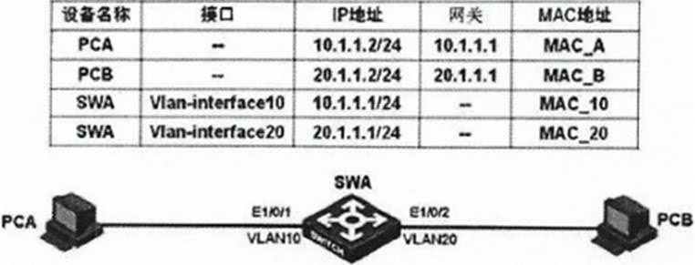
In the network shown in the figure, the corresponding configuration is completed on the switch SWA, and the switch SWA and each PC have learned the corresponding ARP.
PCA accesses PCB and sends an ICMP request message. Switch SWA forwards which of the following MAC address to PCB?
- A . MAC_A
- B . MAC10
- C . MAC20
- D . 0000.0000.0000
The figure shows the networking application of RRPP. The customer LAN switches SWA, SWB, SWC, and SWD form the RRPP ring main ring 1, switches SWB, SWC, and SWE form sub-ring 2, and switches SWB, SWC, and SWF form sub-ring 3. If switch SWE is the master node of sub-ring 2, SWF is the master node of sub-ring 3, and switch SWB is the edge node of sub-ring 2 and sub-ring 3, in order to eliminate the defect of broadcast storm under specific conditions of RRPP dual-homing networking, which of the following can be known from the above information?
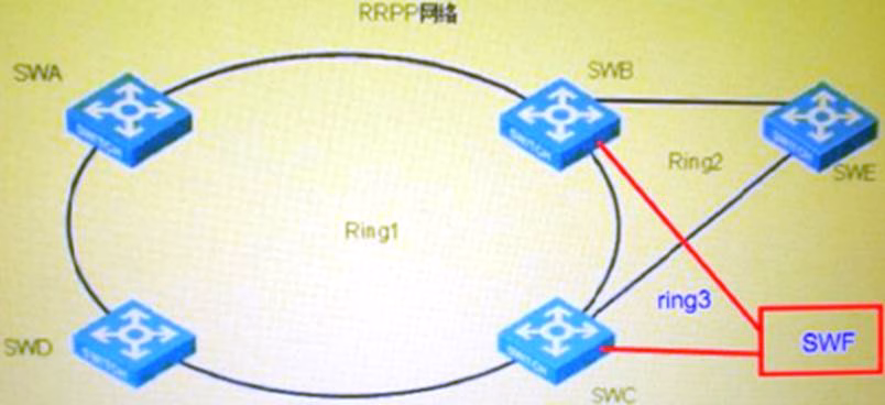
- A . If the link between switch SWA and switch SWD is down, the edge port on switch SWB will be blocked.
- B . If the link between switch SWB and switch SWC is in Down state, the edge port on switch SWB will be blocked.
- C . If the link between switch SWA and switch SWB is down, and the link between switch SWB and switch SWC is down, the edge port on switch SWB will be blocked.
- D . If the link between switch SWA and switch SWB is down, and the link between switch SWA and switch SWD is down, the edge port on switch SWB will be blocked.
In the switching network shown in the figure, VLAN10 is set as lsolate-user-vlan VLAN2 and VLAN3 as the Secondary VLAN of VLAN 10 on switch SWA; VLAN2-VLAN20 is created on switch SWB, and VLAN20 is set as lsolate-user-vlan, and VLAN4 is the Secondary VLAN of VLAN20. After setting the IP addresses of each device as shown in the figure, which of the following statements are correct?
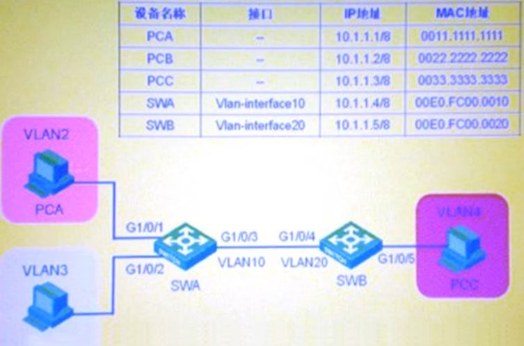
- A . PCA’s message enters from SWA’s GigabitEther1/0/1 port and exits from GigabitEther1/0/3 port without VLAN Tag.
- B . PCA’s message comes out from SWA’s GigabitEthem1/0/3 port and enters SWB’s GigabitEthe1/0/3 port. The VLAN tag it carries is VLAN2.
- C . When SWB accesses PCA, the VLAN tag of the message from SWB’s GigabitEthem1/0/4 is VLAN 1.
- D . SWB’s message enters from SWA’s GigabitEthem1/0/3 port, and the VLAN tag it carries after exiting from GigabitEthem1/0/1 port is VLAN2
As shown in the figure, the switches all run RSTP. Initially, SWA, SWB and SWC are interconnected through links 1, 2 and 3. When the network connection undergoes the following changes, which of the following is the correct statement?
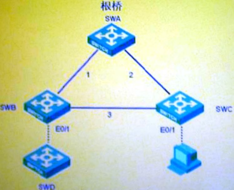
- A . When the link between SWB and SWC is DOWN, both SWB and SWC will send RST BPDU with TC set.
- B . As shown in the figure, when SWB is connected to another switch SWD running RSTP, SWB will send RSTBPDU with TC set.
- C . As shown in the figure, when SWB is connected to another switch SWD running RSTP, SWD will send RSTBPDU with TC set.
- D . When the edge port EO/1 of SWC is connected to a PC, SWC will send a RST BPDU with TC set.
SWA/SWB/SWC are in the same MSTP region and configured with the same region configuration
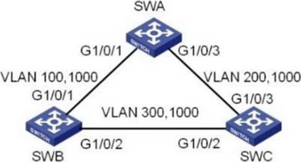
Stp region-configuration region-name h3c
Instance 1 vlan 10
Instance 2 vlan 20
Instance 2 vlan 30
Active region-configuration
The ports of the three interconnected links are all Access and belong to the VLANs identified in the figure. The three switches create VLAN virtual interfaces corresponding to the Access links and run OSPF on the virtual interfaces. The IP addresses of the VLAN virtual interfaces are assigned as follows:
SWA: vlan-interface 10 (192.168.10.1); vlan-interface 30 (192.168.30.1)
SWB: vlan-interface 10 (192.168.10.2); vlan-interface 20 (192.168.20.1)
SWC: vlan-interface 20 (192.168.20.2); vlan-interface 30 (192.168.30.2)
When all interconnected ports are UP and STP and OSPF calculations are complete, which of the following descriptions of network connectivity are correct?
- A . The three switches can establish OSPF neighbor relationships between each other
- B . Two of the three switches cannot establish an OSPF neighbor relationship
- C . All interconnected addresses of the three switches are reachable to each other
- D . Among the 6 interconnected addresses, at least two interconnected addresses are unreachable to each other
When the host receives the GeneralQuery message from the IGMPV2 querier?
- A . The host immediately sends a MembershipReport message
- B . The destination address of the Report message is the same as the GroupAddress in the message
- C . The destination address of the Report message is 224.0.0.1
- D . The host will send a Membership Report message only after receiving a General Query.
Two routers are connected together through a LAN to form a VRRP backup group. The configuration on each interface is as follows:
[RTA-GigabitEthernet1/0] display this
IP address 192.168.0.252 255.255.255.0
Vrrp vrid 1 virtual-ip 192.168.1.254
Vrrp vrid 1 priority 120
[RTB-GigabitEthernet1/0] display this
IP address 192.168.0.253 255.255.255.0
Vrrp vrid 1 virtual-ip 192.168.1.254
What can we learn from the above information?
- A . RTA is the Master router of the backup group
- B . RTB is the Master router of the backup group
- C . RTA and RTB are both in VRRP Initialize state
- D . RTA and RTB are both in VRRP Master state
Latest GB0-372-ENU Dumps Valid Version with 432 Q&As
Latest And Valid Q&A | Instant Download | Once Fail, Full Refund
