

Review the VPN configuration shown in the exhibit.
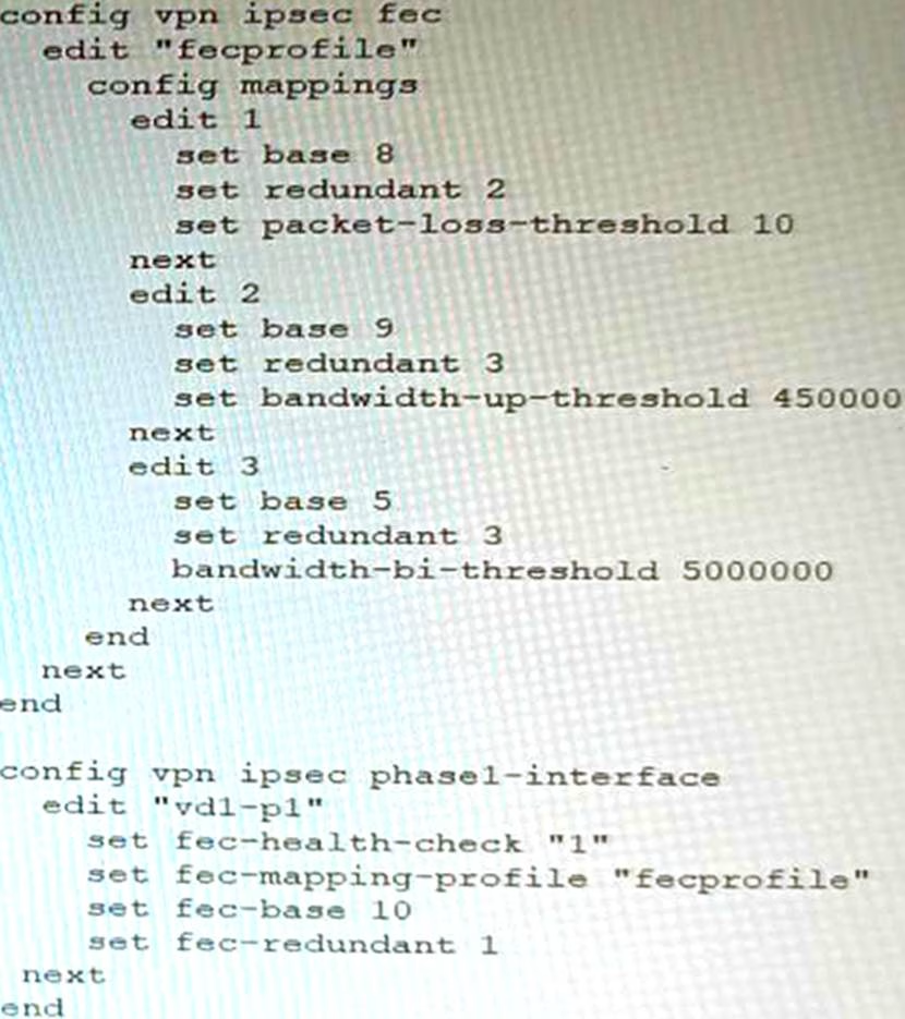

What is the Forward Error Correction behavior if the SD-WAN network traffic download is 500 Mbps and has 8% of packet loss in the environment?
- A . 1 redundant packet for every 10 base packets
- B . 3 redundant packet for every 5 base packets
- C . 2 redundant packet for every 8 base packets
- D . 3 redundant packet for every 9 base packets
C
Explanation:
The FEC configuration in the exhibit specifies that if the packet loss is greater than 10%, then the FEC mapping will be 8 base packets and 2 redundant packets. The download bandwidth of 500 Mbps is not greater than 950 Mbps, so the FEC mapping is not overridden by the bandwidth setting. Therefore, the FEC behavior will be 2 redundant packets for every 8 base packets.
Here is the explanation of the FEC mappings in the exhibit:
Packet loss greater than 10%: 8 base packets and 2 redundant packets.
Upload bandwidth greater than 950 Mbps: 9 base packets and 3 redundant packets.
The mappings are matched from top to bottom, so the first mapping that matches the conditions will be used. In this case, the first mapping matches because the packet loss is greater than 10%. Therefore, the FEC behavior will be 2 redundant packets for every 8 base packets.
Reference: https://docs.fortinet.com/document/fortigate/7.0.0/new-features/169010/adaptive-forward-error-correction-7-0-2
You are running a diagnose command continuously as traffic flows through a platform with NP6 and you obtain the following output:
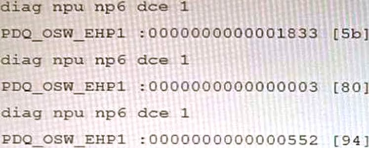

Given the information shown in the output, which two statements are true? (Choose two.)
- A . Enabling bandwidth control between the ISF and the NP will change the output
- B . The output is showing a packet descriptor queue accumulated counter
- C . Enable HPE shaper for the NP6 will change the output
- D . Host-shortcut mode is enabled.
- E . There are packet drops at the XAUI.
BE
Explanation:
The diagnose command shown in the output is used to display information about NP6 packet descriptor queues. The output shows that there are 16 NP6 units in total, and each unit has four XAUI ports (XA0-XA3). The output also shows that there are some non-zero values in the columns PDQ ACCU (packet descriptor queue accumulated counter) and PDQ DROP (packet descriptor queue drop counter). These values indicate that there are some packet descriptor queues that have reached their maximum capacity and have dropped some packets at the XAUI ports. This could be caused by congestion or misconfiguration of the XAUI ports or the ISF (Internal Switch Fabric).
References: https://docs.fortinet.com/document/fortigate/7.0.0/cli-reference/19662/diagnose-np6-pdq
The output is showing a packet descriptor queue accumulated counter, which is a measure of the number of packets that have been dropped by the NP6 due to congestion. The counter will increase if there are more packets than the NP6 can handle, which can happen if the bandwidth between the ISF and the NP is not sufficient or if the HPE shaper is enabled.
The output also shows that there are packet drops at the XAUI, which is the interface between the NP6 and the FortiGate’s backplane. This means that the NP6 is not able to keep up with the traffic and is dropping packets.
The other statements are not true. Host-shortcut mode is not enabled, and enabling bandwidth control between the ISF and the NP will not change the output. HPE shaper is a feature that can be enabled to improve performance, but it will not change the output of the diagnose command.
Reference: https://docs.fortinet.com/document/fortigate/7.4.0/hardware-acceleration/48875/diagnose-npu-np6-dce-np6-id-number-of-dropped-np6-packets
Which two methods are supported for importing user defined Lookup Table Data into the FortiSIEM? (Choose two.)
- A . Report
- B . FTP
- C . API
- D . SCP
AC
Explanation:
FortiSIEM supports two methods for importing user defined Lookup Table Data:
Report: You can import lookup table data from a report. This is the most common method for importing lookup table data.
API: You can also import lookup table data using the FortiSIEM API. This is a more advanced method that allows you to import lookup table data programmatically.
FTP, SCP, and other file transfer protocols are not supported for importing lookup table data into FortiSIEM.
Reference: https://help.fortinet.com/fsiem/6-7-4/Online-Help/HTML5_Help/importing_lookup_table_data.htm
What is the benefit of using FortiGate NAC LAN Segments?
- A . It provides support for multiple DHCP servers within the same VLAN.
- B . It provides physical isolation without changing the IP address of hosts.
- C . It provides support for IGMP snooping between hosts within the same VLAN
- D . It allows for assignment of dynamic address objects matching NAC policy.
D
Explanation:
FortiGate NAC LAN Segments are a feature that allows users to assign different VLANs to different LAN segments without changing the IP address of hosts or bouncing the switch port. This provides physical isolation while maintaining firewall sessions and avoiding DHCP issues. One benefit of using FortiGate NAC LAN Segments is that it allows for assignment of dynamic address objects matching NAC policy. This means that users can create firewall policies based on dynamic address objects that match the NAC policy criteria, such as device type, OS type, MAC address, etc. This simplifies firewall policy management and enhances security by applying different security profiles to different types of devices. References: https://docs.fortinet.com/document/fortigate/7.0.0/new-features/856212/nac-lan-segments-7-0-1
You are troubleshooting a FortiMail Cloud service integrated with Office 365 where outgoing emails are not reaching the recipients’ mail.
What are two possible reasons for this problem? (Choose two.)
- A . The FortiMail access control rule to relay from Office 365 servers FQDN is missing.
- B . The FortiMail DKIM key was not set using the Auto Generation option.
- C . The FortiMail access control rules to relay from Office 365 servers public IPs are missing.
- D . A Mail Flow connector from the Exchange Admin Center has not been set properly to the FortiMail Cloud FQDN.
AD
Explanation:
Refer to the exhibit.

FortiManager is configured with the Jinja Script under CLI Templates shown in the exhibit.
Which two statements correctly describe the expected behavior when running this template? (Choose two.)
- A . The Jinja template will automatically map the interface with "WAN" role on the managed FortiGate.
- B . The template will work if you change the variable format to $(WAN).
- C . The template will work if you change the variable format to {{WAN}}.
- D . The administrator must first manually map the interface for each device with a meta field.
- E . The template will fail because this configuration can only be applied with a CLI or TCL script.
DE
Explanation:
D. The administrator must first manually map the interface for each device with a meta field.
The Jinja template in the exhibit is expecting a meta field called WAN to be set on the managed FortiGate. This meta field will specify which interface on the FortiGate should be assigned the "WAN" role. If the meta field is not set, then the template will fail.
E. The template will fail because this configuration can only be applied with a CLI or TCL script.
The Jinja template in the exhibit is trying to configure the interface role on the managed FortiGate. This type of configuration can only be applied with a CLI or TCL script. The Jinja template will fail
because it is not a valid CLI or TCL script.
SD-WAN is configured on a FortiGate. You notice that when one of the internet links has high latency the time to resolve names using DNS from FortiGate is very high.
You must ensure that the FortiGate DNS resolution times are as low as possible with the least amount of work.
What should you configure?
- A . Configure local out traffic to use the outgoing interface based on SD-WAN rules with a manual defined IP associated to a loopback interface and configure an SD-WAN rule from the loopback to the DNS server.
- B . Configure an SD-WAN rule to the DNS server and use the FortiGate interface IPs in the source address.
- C . Configure two DNS servers and use DNS servers recommended by the two internet providers.
- D . Configure local out traffic to use the outgoing interface based on SD-WAN rules with the interface IP and configure an SD-WAN rule to the DNS server.
D
Explanation:
SD-WAN is a feature that allows users to optimize network performance and reliability by using multiple WAN links and applying rules based on various criteria, such as latency, jitter, packet loss, etc. One way to ensure that the FortiGate DNS resolution times are as low as possible with the least amount of work is to configure local out traffic to use the outgoing interface based on SD-WAN rules with the interface IP and configure an SD-WAN rule to the DNS server. This means that the FortiGate will use the best WAN link available to send DNS queries to the DNS server according to the SD-WAN rule, and use its own interface IP as the source address. This avoids NAT issues and ensures optimal DNS performance. References: https://docs.fortinet.com/document/fortigate/7.0.0/sd-wan/19662/sd-wan
Refer to the exhibits.
Exhibit A
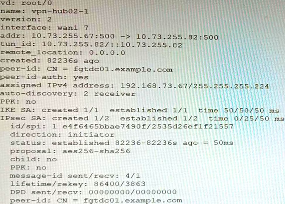

Exhibit B
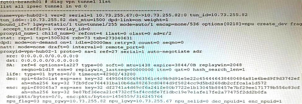

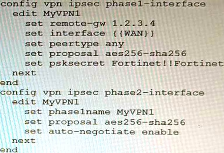
Exhibit C
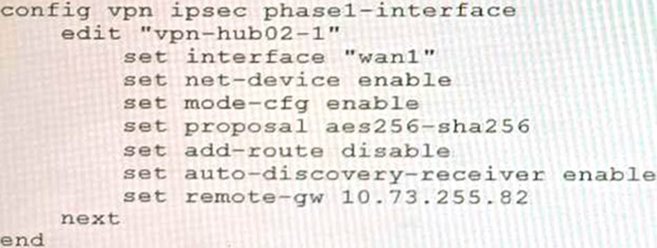

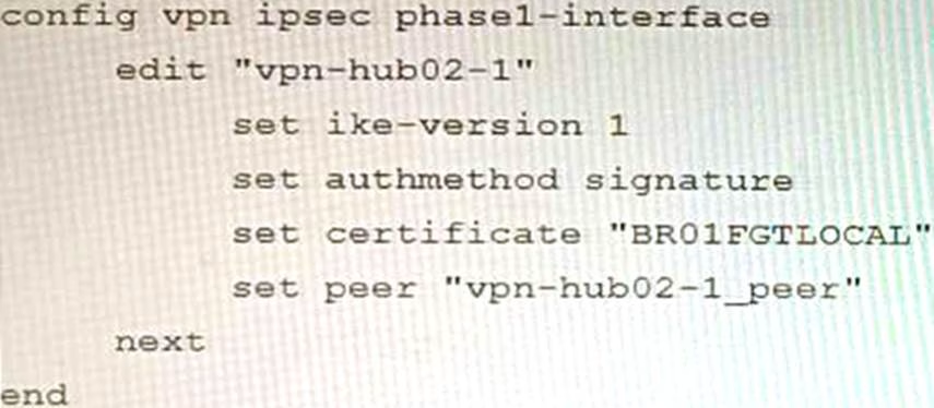
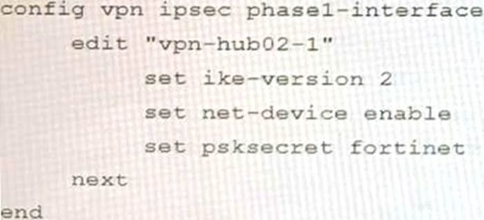
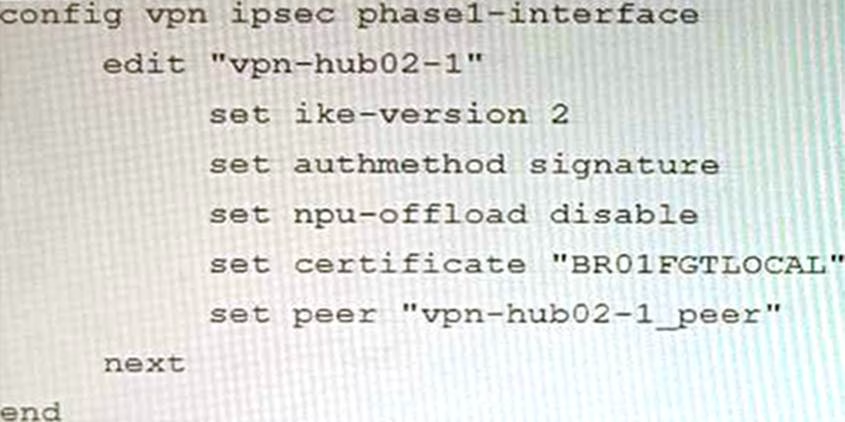
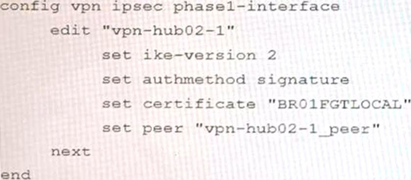
A customer is trying to set up a VPN with a FortiGate, but they do not have a backup of the configuration. Output during a troubleshooting session is shown in the exhibits A and B and a baseline VPN configuration is shown in Exhibit C Referring to the exhibits, which configuration will restore VPN connectivity?
A)

B)

C)

D)

- A . Option A
- B . Option B
- C . Option C
- D . Option D
C
Explanation:
The output in Exhibit A shows that the VPN tunnel is not established because the peer IP address is incorrect. The output in Exhibit B shows that the peer IP address is 192.168.1.100, but the baseline VPN configuration in Exhibit C shows that the peer IP address should be 192.168.1.101.
To restore VPN connectivity, you need to change the peer IP address in the VPN tunnel configuration to 192.168.1.101.
The correct configuration is shown below: config vpn ipsec phase1-interface edit "wan"
set peer-ip 192.168.1.101
set peer-id 192.168.1.101
set dhgrp 1
set auth-mode psk
set psk SECRET_PSK
next
end
Option A is incorrect because it does not change the peer IP address. Option B is incorrect because it changes the peer IP address to 192.168.1.100, which is the incorrect IP address. Option D is incorrect because it does not include the necessary configuration for the VPN tunnel.
An HA topology is using the following configuration:
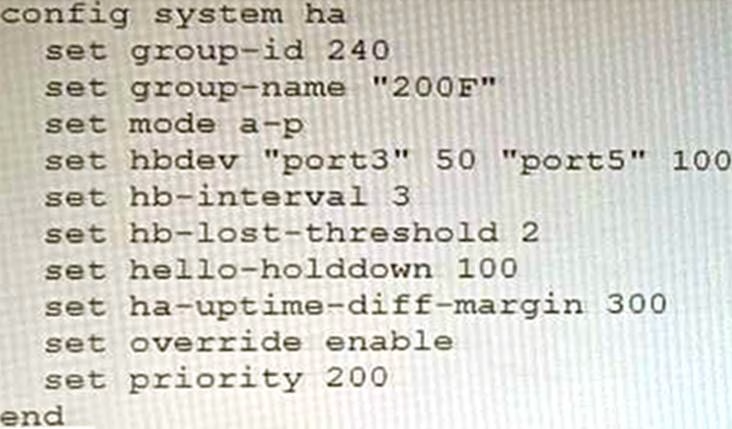

Based on this configuration, how long will it take for a failover to be detected by the secondary cluster member?
- A . 600ms
- B . 200ms
- C . 300ms
- D . 100ms
B
Explanation:
The HA heartbeat interval is 100ms, and the number of lost heartbeats before a failover is detected is 2. So, it will take 2 * 100ms = 200ms for a failover to be detected by the secondary cluster member.
Reference: FortiGate High Availability: https://docs.fortinet.com/document/fortigate/7.0.0/administration-guide/647723/link-monitoring-and-ha-failover-time
Refer to the exhibit.
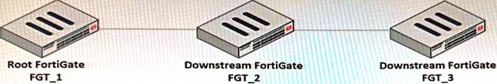

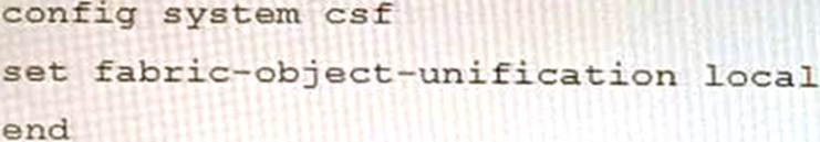
You have deployed a security fabric with three FortiGate devices as shown in the exhibit. FGT_2 has the following configuration:

FGT_1 and FGT_3 are configured with the default setting.
Which statement is true for the synchronization of fabric-objects?
- A . Objects from the FortiGate FGT_2 will be synchronized to the upstream FortiGate.
- B . Objects from the root FortiGate will only be synchronized to FGT__2.
- C . Objects from the root FortiGate will not be synchronized to any downstream FortiGate.
- D . Objects from the root FortiGate will only be synchronized to FGT_3.
C
Explanation:
The fabric-object-unification setting on FGT_2 is set to local, which means that objects will not be synchronized to any other FortiGate devices in the security fabric. The default setting for fabric-object-unification is default, which means that objects will be synchronized from the root FortiGate to all downstream FortiGate devices.
Since FGT_2 is not the root FortiGate and the fabric-object-unification setting is set to local, objects from the root FortiGate will not be synchronized to FGT_2.
Reference: Synchronizing objects across the Security Fabric: https://docs.fortinet.com/document/fortigate/6.4.0/administration-guide/880913/synchronizing-objects-across-the-security-fabric
Refer to the exhibit.
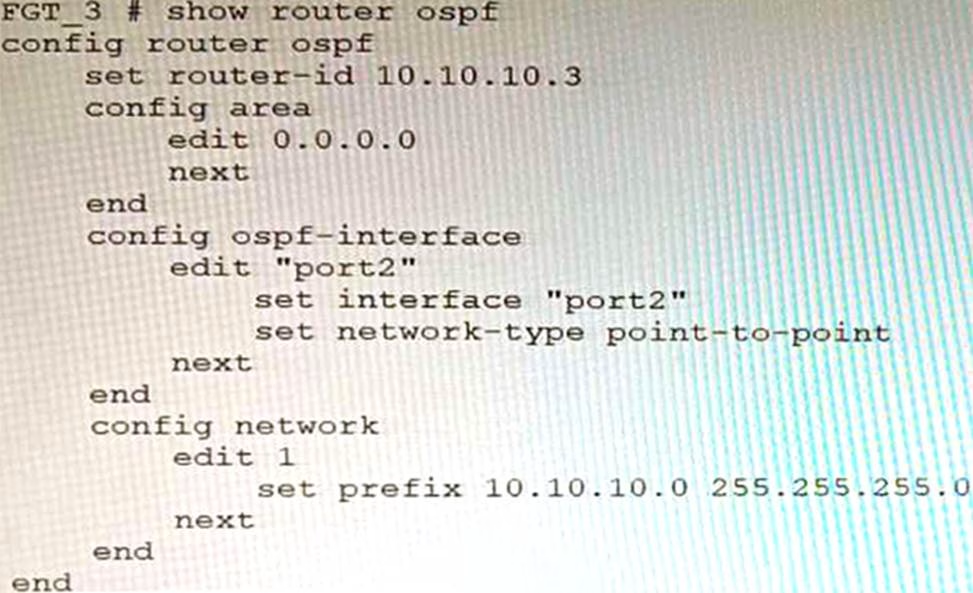

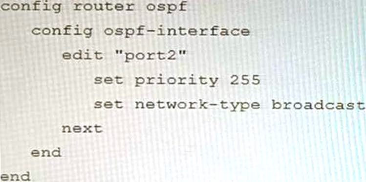
You are operating an internal network with multiple OSPF routers on the same LAN segment. FGT_3 needs to be added to the OSPF network and has the configuration shown in the exhibit. FGT_3 is not establishing any OSPF connection.
What needs to be changed to the configuration to make sure FGT_3 will establish OSPF neighbors without affecting the DR/BDR election?
A)
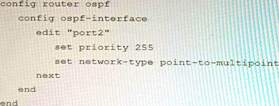

B)
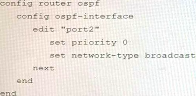

C)

D)
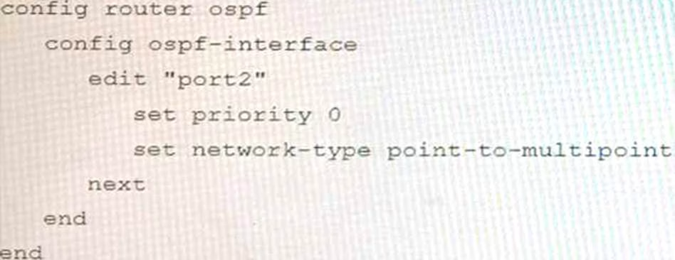

- A . Option A
- B . Option B
- C . Option C
- D . Option D
B
Explanation:
The OSPF configuration shown in the exhibit is using the default priority value of 1 for the interface port1. This means that FGT_3 will participate in the DR/BDR election process with the other OSPF routers on the same LAN segment. However, this is not desirable because FGT_3 is a new device that needs to be added to the OSPF network without affecting the existing DR/BDR election. Therefore, to make sure FGT_3 will establish OSPF neighbors without affecting the DR/BDR election, the priority value of the interface port1 should be changed to 0. This will prevent FGT_3 from becoming a DR or BDR and allow it to form OSPF adjacencies with the current DR and BDR. Option B shows the correct configuration that changes the priority value to 0. Option A is incorrect because it does not change the priority value. Option C is incorrect because it changes the network type to point-to-point, which is not suitable for a LAN segment with multiple OSPF routers. Option D is incorrect because it changes the area ID to 0.0.0.1, which does not match the area ID of the other OSPF routers on the same LAN segment. References: https://docs.fortinet.com/document/fortigate/7.0.0/administration-guide/358640/basic-ospf-example
A retail customer with a FortiADC HA cluster load balancing five webservers in L7 Full NAT mode is receiving reports of users not able to access their website during a sale event. But for clients that were able to connect, the website works fine.
CPU usage on the FortiADC and the web servers is low, application and database servers are still able to handle more traffic, and the bandwidth utilization is under 30%.
Which two options can resolve this situation? (Choose two.)
- A . Change the persistence rule to LB_PERSIS_SSL_SESSJD.
- B . Add more web servers to the real server poof
- C . Disable SSL between the FortiADC and the web servers
- D . Add a connection-pool to the FortiADC virtual server
BD
Explanation:
Option B: Adding more web servers to the real server pool will increase the overall capacity of the load balancer, which should help to resolve the issue of users not being able to access the website. Option D: Adding a connection-pool to the FortiADC virtual server will allow the load balancer to cache connections to the web servers, which can help to improve performance and reduce the number of dropped connections.
Option A: Changing the persistence rule to LB_PERSIS_SSL_SESSJD would only be necessary if the current persistence rule is not working properly. In this case, the CPU usage on the FortiADC and the web servers is low, so the persistence rule is likely not the issue.
Option C: Disabling SSL between the FortiADC and the web servers would reduce the load on the FortiADC, but it would also make the website less secure. Since the bandwidth utilization is under 30%, it is unlikely that disabling SSL would resolve the issue.
Reference: https://docs.fortinet.com/document/fortiadc/7.2.1/handbook/970956/configuring-virtual-servers
Refer to the CLI output:
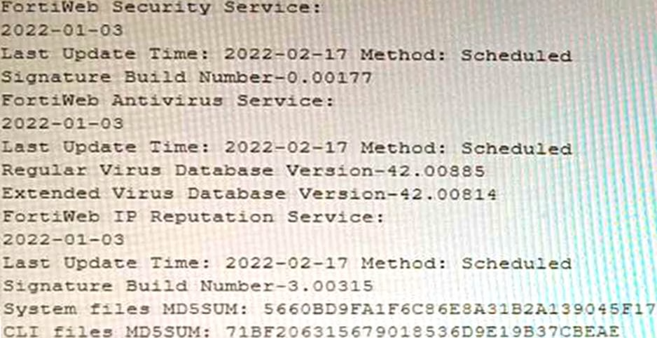

Given the information shown in the output, which two statements are correct? (Choose two.)
- A . Geographical IP policies are enabled and evaluated after local techniques.
- B . Attackers can be blocked before they target the servers behind the FortiWeb.
- C . The IP Reputation feature has been manually updated
- D . An IP address that was previously used by an attacker will always be blocked
- E . Reputation from blacklisted IP addresses from DHCP or PPPoE pools can be restored
BE
Explanation:
The CLI output shown in the exhibit indicates that FortiWeb has enabled IP Reputation feature with local techniques enabled and geographical IP policies enabled after local techniques (set geoip-policy-order after-local). IP Reputation feature is a feature that allows FortiWeb to block or allow traffic based on the reputation score of IP addresses, which reflects their past malicious activities or behaviors. Local techniques are methods that FortiWeb uses to dynamically update its own blacklist based on its own detection of attacks or violations from IP addresses (such as signature matches, rate limiting, etc.). Geographical IP policies are rules that FortiWeb uses to block or allow traffic based on the geographical location of IP addresses (such as country, region, city, etc.). Therefore, based on the output, one correct statement is that attackers can be blocked before they target the servers behind the FortiWeb. This is because FortiWeb can use IP Reputation feature to block traffic from IP addresses that have a low reputation score or belong to a blacklisted location, which prevents them from reaching the servers and launching attacks. Another correct statement is that reputation from blacklisted IP addresses from DHCP or PPPoE pools can be restored. This is because FortiWeb can use local techniques to remove IP addresses from its own blacklist if they stop sending malicious traffic for a certain period of time (set local-techniques-expire-time), which allows them to regain their reputation and access the servers. This is useful for IP addresses that are dynamically assigned by DHCP or PPPoE and may change frequently. References:
https://docs.fortinet.com/document/fortiweb/6.4.0/administration-guide/19662/ip-reputation
https://docs.fortinet.com/document/fortiweb/6.4.0/administration-guide/19662/geographical-ip-policies
Refer to the exhibit.


You are deploying a FortiGate 6000F. The device should be directly connected to a switch. In the future, a new hardware module providing higher speed will be installed in the switch, and the connection to the FortiGate must be moved to this higher-speed port.
You must ensure that the initial FortiGate interface connected to the switch does not affect any other port when the new module is installed and the new port speed is defined.
How should the initial connection be made?
- A . Connect the switch on any interface between ports 21 to 24
- B . Connect the switch on any interface between ports 25 to 28
- C . Connect the switch on any interface between ports 1 to 4
- D . Connect the switch on any interface between ports 5 to 8.
C
Explanation:
The FortiGate 6000F has 24 1/10/25-Gbps SFP28 data network interfaces (1 to 24). These interfaces are divided into the following interface groups: 1 to 4, 5 to 8, 9 to 12, 13 to 16, 17 to 20, and 21 to 24. The ports 25 to 28 are 40/100-Gbps QSFP28 data network interfaces.
The initial connection should be made to any interface between ports 1 to 4. This is because the ports 21 to 24 are part of the same interface group, and changing the speed of one of these ports will affect the speeds of all of the ports in the group. The ports 5 to 8 are also part of the same interface group, so they should not be used for the initial connection.
The new hardware module that will be installed in the switch will provide higher speed ports. When this module is installed, the speed of the ports 21 to 24 will be increased. However, this will not affect the ports 1 to 4, because they are not part of the same interface group.
Therefore, the initial connection should be made to any interface between ports 1 to 4, in order to ensure that the FortiGate interface connected to the switch does not affect any other port when the new module is installed and the new port speed is defined.
Reference: FortiGate 6000F Front Panel Interfaces: https://docs.fortinet.com/document/fortigate-6000/hardware/fortigate-6000f-system-guide/827055/front-panel-interfaces
Which feature must you enable on the BGP neighbors to accomplish this goal?
- A . Graceful-restart
- B . Deterministic-med
- C . Synchronization
- D . Soft-reconfiguration
A
Explanation:
Graceful-restart is a feature that allows BGP neighbors to maintain their routing information during a BGP restart or failover event, without disrupting traffic forwarding or causing route flaps. Graceful-restart works by allowing a BGP speaker (the restarting router) to notify its neighbors (the helper routers) that it is about to restart or failover, and request them to preserve their routing information and forwarding state for a certain period of time (the restart time). The helper routers then mark the routes learned from the restarting router as stale, but keep them in their routing table and continue forwarding traffic based on them until they receive an end-of-RIB marker from the restarting router or until the restart time expires. This way, graceful-restart can minimize traffic disruption and routing instability during a BGP restart or failover event.
References: https://docs.fortinet.com/document/fortigate/7.0.0/cookbook/19662/bgp-graceful-restart
Refer to the exhibit, which shows a Branch1 configuration and routing table.
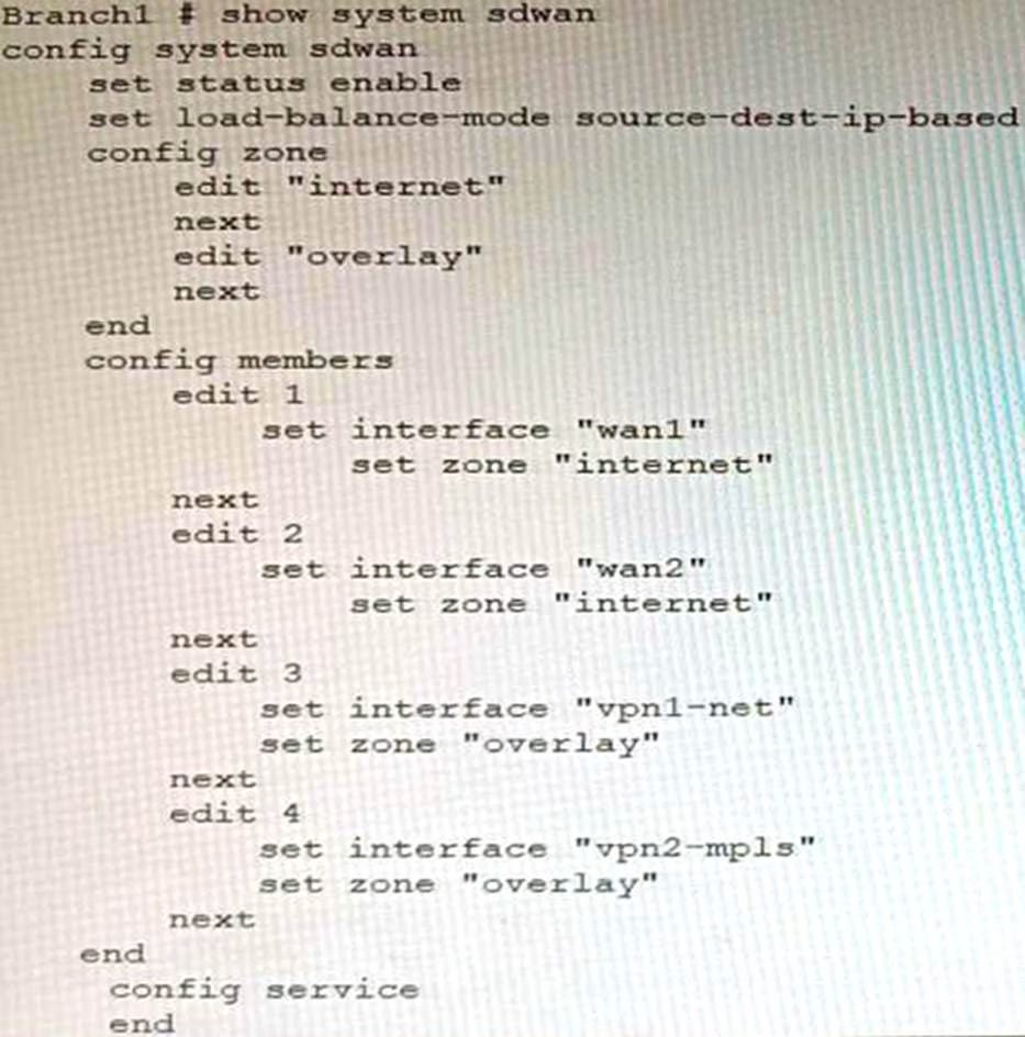

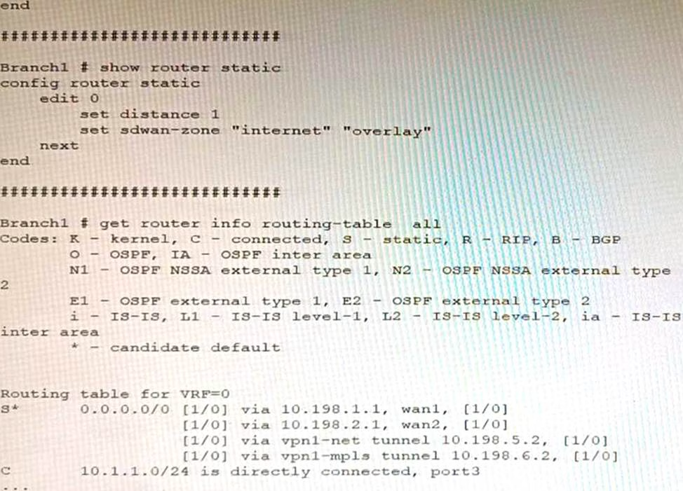

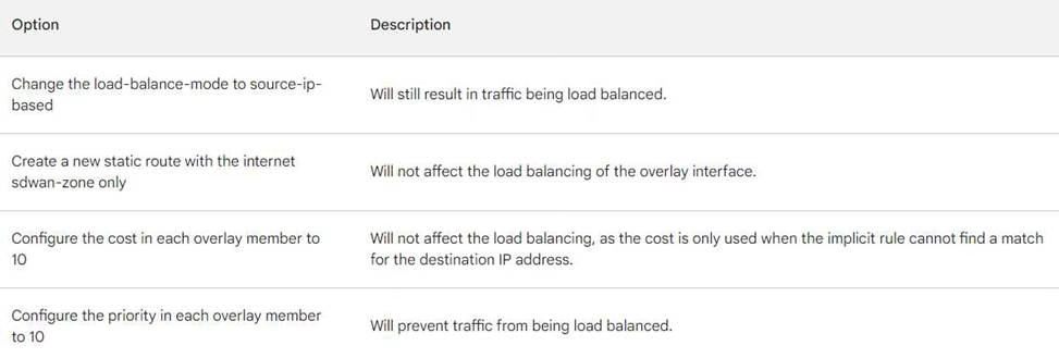
In the SD-WAN implicit rule, you do not want the traffic load balance for the overlay interface when all members are available.
In this scenario, which configuration change will meet this requirement?
- A . Change the load-balance-mode to source-ip-based.
- B . Create a new static route with the internet sdwan-zone only
- C . Configure the cost in each overlay member to 10.
- D . Configure the priority in each overlay member to 10.
D
Explanation:
The default load balancing mode for the SD-WAN implicit rule is source IP based. This means that traffic will be load balanced evenly between the overlay members, regardless of the member’s priority.
To prevent traffic from being load balanced, you can configure the priority of each overlay member to 10. This will make the member ineligible for load balancing.
The other options are not correct. Changing the load balancing mode to source-IP based will still result in traffic being load balanced. Creating a new static route with the internet sdwan-zone only will not affect the load balancing of the overlay interface. Configuring the cost in each overlay member to 10 will also not affect the load balancing, as the cost is only used when the implicit rule cannot find a match for the destination IP address.

Refer to the exhibits.
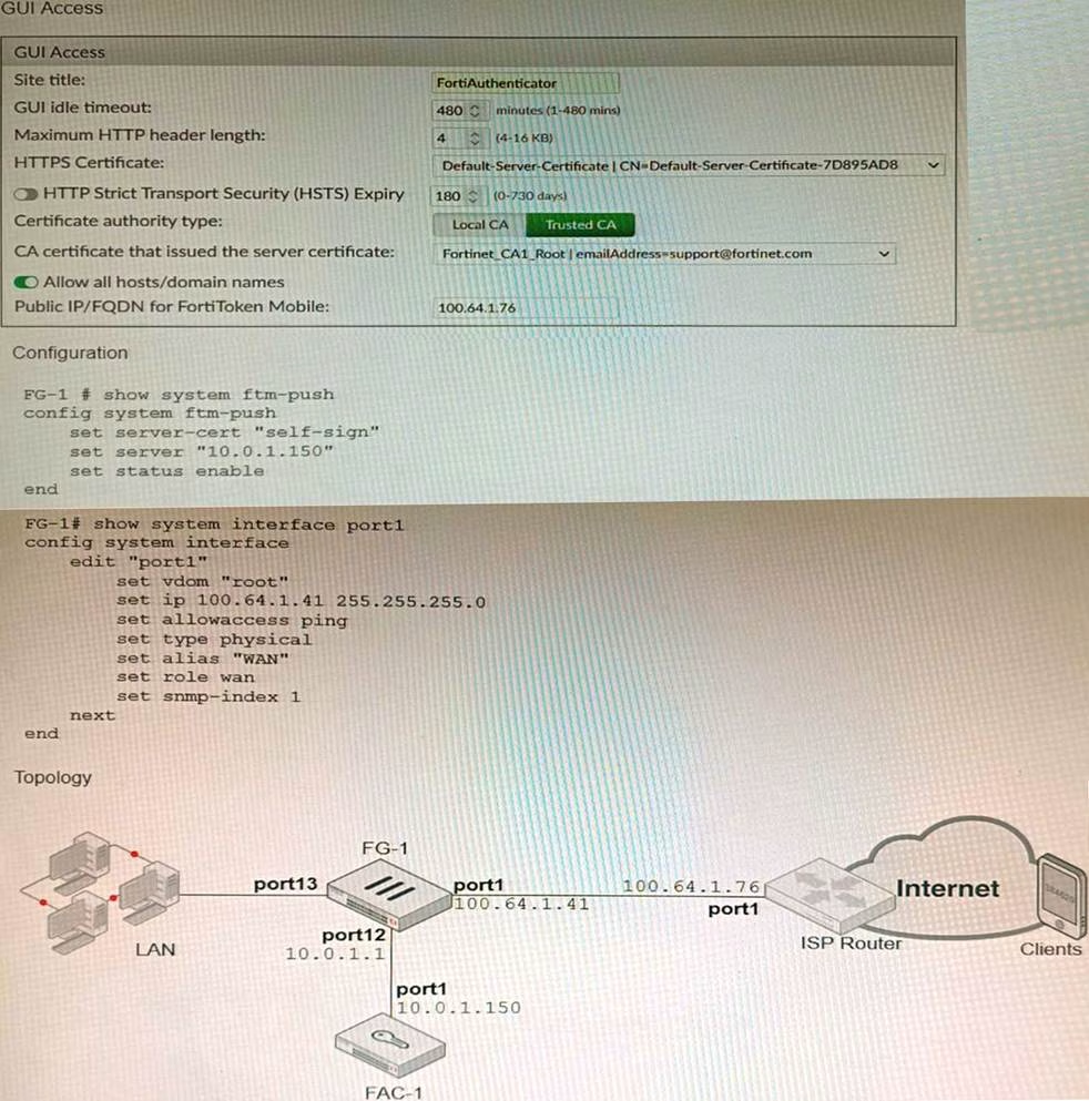

An administrator has configured a FortiGate and Forti Authenticator for two-factor authentication with FortiToken push notifications for their SSL VPN login. Upon initial review of the setup, the administrator has discovered that the customers can manually type in their two-factor code and authenticate but push notifications do not work
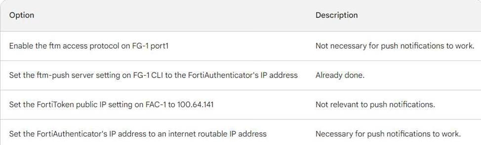
Based on the information given in the exhibits, what must be done to fix this?
- A . On FG-1 port1, the ftm access protocol must be enabled.
- B . FAC-1 must have an internet routable IP address for push notifications.
- C . On FG-1 CLI, the ftm-push server setting must point to 100.64.141.
- D . On FAC-1, the FortiToken public IP setting must point to 100.64.1 41
B
Explanation:
FortiToken push notifications require that the FortiAuthenticator has an internet routable IP address. This is because the FortiAuthenticator uses this IP address to send push notifications to the FortiGate.
The other options are not correct. Enabling the ftm access protocol on FG-1 port1 is not necessary for push notifications to work. The ftm-push server setting on FG-1 CLI should already point to the FortiAuthenticator’s IP address. The FortiToken public IP setting on FAC-1 is not relevant to push notifications.
Here is a table that summarizes the different options:

Refer to the exhibit.
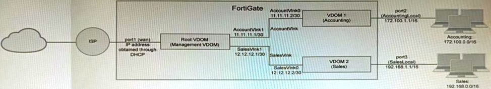

A customer has deployed a FortiGate 300E with virtual domains (VDOMs) enabled in the multi-VDOM mode. There are three VDOMs: Root is for management and internet access, while VDOM 1 and VDOM 2 are used for segregating internal traffic. AccountVInk and SalesVInk are standard VDOM links in Ethernet mode.
Given the exhibit, which two statements below about VDOM behavior are correct? (Choose two.)
- A . You can apply OSPF routing on the VDOM link in either PPP or Ethernet mode
- B . Traffic on AccountVInk and SalesVInk will not be accelerated.
- C . The VDOM links are in Ethernet mode because they have IP addressed assigned on both sides.
- D . Root VDOM is an Admin type VDOM, while VDOM 1 and VDOM 2 are Traffic type VDOMs.
- E . OSPF routing can be configured between VDOM 1 and Root VDOM without any configuration changes to AccountVInk
AD
Explanation:
You are responsible for recommending an adapter type for NICs on a FortiGate VM that will run on an ESXi Hypervisor. Your recommendation must consider performance as the main concern, cost is not a factor.
Which adapter type for the NICs will you recommend?
- A . Native ESXi Networking with E1000
- B . Virtual Function (VF) PCI Passthrough
- C . Native ESXi Networking with VMXNET3
- D . Physical Function (PF) PCI Passthrough
C
Explanation:
The FortiGate VM is a virtual firewall appliance that can run on various hypervisors, such as ESXi, Hyper-V, KVM, etc. The adapter type for NICs on a FortiGate VM determines the performance and compatibility of the network interface cards with the hypervisor and the physical network. There are different adapter types available for NICs on a FortiGate VM, such as E1000, VMXNET3, SR-IOV, etc. If performance is the main concern and cost is not a factor, one option is to use native ESXi networking with VMXNET3 adapter type for NICs on a FortiGate VM that will run on an ESXi hypervisor. VMXNET3 is a paravirtualized network interface card that is optimized for performance in virtual machines and supports features such as multiqueue support, Receive Side Scaling (RSS), Large Receive Offload (LRO), IPv6 offloads, and MSI/MSI-X interrupt delivery. Native ESXi networking means that the FortiGate VM uses the standard virtual switch (vSwitch) or distributed virtual switch (dvSwitch) provided by the ESXi hypervisor to connect to the physical network. This option can provide high performance and compatibility for NICs on a FortiGate VM without requiring additional hardware or software components.
References:
https://docs.fortinet.com/document/fortigate/7.0.0/vm-installation-for-vmware-esxi/19662/installing-fortigate-vm-on-vmware-esxi
https://docs.fortinet.com/document/fortigate/7.0.0/vm-installation-for-vmware-esxi/19662/networking
You are deploying a FortiExtender (FEX) on a FortiGate-60F. The FEX will be managed by the FortiGate. You anticipate high utilization. The requirement is to minimize the overhead on the device for WAN traffic.
Which action achieves the requirement in this scenario?
- A . Add a switch between the FortiGate and FEX.
- B . Enable CAPWAP connectivity between the FortiGate and the FortiExtender.
- C . Change connectivity between the FortiGate and the FortiExtender to use VLAN Mode
- D . Add a VLAN under the FEX-WAN interface on the FortiGate.
C
Explanation:
VLAN Mode is a more efficient way to connect a FortiExtender to a FortiGate than CAPWAP Mode. This is because VLAN Mode does not require the FortiExtender to send additional control traffic to the FortiGate.
The other options are not correct.