

A customer notices a platform engineer intentionally leaving a 1U gap underneath a Dell PowerScale H400 chassis during racking and stacking What is the purpose of the gap?
- A . Backend Ethernet switch
- B . Cable management tray
- C . Location to install archive nodes
- D . Required blanking panel for node separation
B
Explanation:
During the installation of Dell PowerScale H400 nodes, it is standard practice to leave a 1U gap underneath the chassis to accommodate the Cable Management Tray (CMT). The Cable Management Tray is essential for organizing and supporting the network and power cables connected to the node. Proper cable management ensures that cables are neatly routed, reduces stress on the connectors, and prevents obstruction of airflow within the rack.
According to the Dell PowerScale Hardware Installation and Planning Guide, the inclusion of a Cable Management Tray improves serviceability and maintains optimal airflow by preventing cables from hanging in front of the equipment or blocking ventilation paths. By intentionally leaving a 1U gap, the platform engineer ensures that the Cable Management Tray can be installed without interfering with the node’s operation or the rack’s structural integrity.
Reference: Dell PowerScale Hardware Installation and Planning Guide
Best Practices for Cable Management in Dell PowerScale Systems
Which cluster interface provides the most detailed network traffic statistics and enables file and directory operations on the cluster?
- A . Web console
- B . Serial console
- C . Platform API
- D . CLI
D
Explanation:
The Command Line Interface (CLI) provides the most comprehensive and detailed interaction with a Dell PowerScale cluster. Through the CLI, administrators have access to a wide range of commands that offer detailed network traffic statistics, system performance metrics, and the ability to perform granular file and directory operations.
While the Web console offers a user-friendly graphical interface for cluster management, it may not provide the same level of detail or the full set of functionalities available in the CLI. The Serial console is primarily used for initial setup or troubleshooting when network access is unavailable. The Platform API allows for programmatic access but requires additional development effort to utilize. The CLI is accessible via SSH and provides tools like isi statistics for detailed performance metrics and isi commands for file system operations. This makes it the most powerful interface for administrators needing in-depth information and control over the cluster.
Reference: Dell PowerScale OneFS Command-Line Administration Guide Dell PowerScale OneFS CLI Reference Guide
A platform engineer is connecting a new Dell PowerScale F600 node to the frontend switch in an existing cluster with legacy nodes.
How should the network cables be connected?
- A . From the PCIe slot 1 to the frontend Ethernet switch
- B . From the PCIe slot 3 to the frontend Ethernet switch
- C . From the PCIe slot 1 to the frontend InfiniBand switch
- D . From the PCIe slot 3 to the frontend InfiniBand switch
A
Explanation:
When connecting a Dell PowerScale F600 node to the frontend network in an existing cluster with legacy nodes, it’s important to follow the correct cabling practices to ensure network compatibility and optimal performance.
The F600 node uses PCIe slot 1 for frontend (client) network connections. This slot supports Ethernet network interfaces that handle client traffic. PCIe slot 3 is typically reserved for backend (cluster interconnect) networking. Since the cluster includes legacy nodes, and assuming they use Ethernet for frontend connectivity, the F600 should connect its frontend network interfaces from PCIe slot 1 to the frontend Ethernet switch.
Connecting the cables from PCIe slot 1 to the frontend Ethernet switch ensures that the F600 node properly communicates with clients and integrates seamlessly into the existing cluster network infrastructure.
Reference: Dell PowerScale F600 Technical Specifications Guide
Dell PowerScale Network Configuration Guide
Best Practices for Adding Nodes to an Existing Dell PowerScale Cluster
A platform engineer connected to a Dell PowerScale F600 node using a serial connection. The session is unresponsive.
What action must the engineer take?
- A . Restart the server using the front panel power button.
- B . Check the settings of the serial connection.
- C . Replace the serial cable with a new one.
- D . Update the node firmware to the latest release
B
Explanation:
When a platform engineer connects to a Dell PowerScale F600 node using a serial connection and the session is unresponsive, the first action should be to check the settings of the serial connection. Serial communication requires specific configuration parameters to establish a successful connection. An incorrect setting can result in an unresponsive session.
The standard serial connection settings for Dell PowerScale nodes are:
Baud Rate: 115200
Data Bits: 8
Parity: None
Stop Bits: 1
Flow Control: None
Steps to resolve the issue:
Verify Serial Port Configuration:
Open your terminal emulator software (e.g., PuTTY, Tera Term). Check that the serial port settings match the required parameters. Confirm Physical Connections:
Ensure that the serial cable is securely connected to both the laptop and the node’s serial port.
Test the Serial Cable:
If possible, test the cable with another device to rule out a faulty cable.
Restarting the server or updating firmware is unnecessary at this stage and could introduce
additional issues. Replacing the serial cable should only be considered after confirming that the
settings and connections are correct.
Reference: Dell PowerScale Hardware Installation and Planning Guide C Serial Connection Settings
Dell PowerScale OneFS CLI Administration Guide C Accessing the Cluster Through a Serial Connection Dell Knowledge Base Article C Troubleshooting Serial Console Access
DRAG DROP
A platform engineer is creating a Dell PowerScale cluster using the Configuration Wizard. They have selected the Create a new cluster option.
What Is the correct sequence of steps to create the cluster?
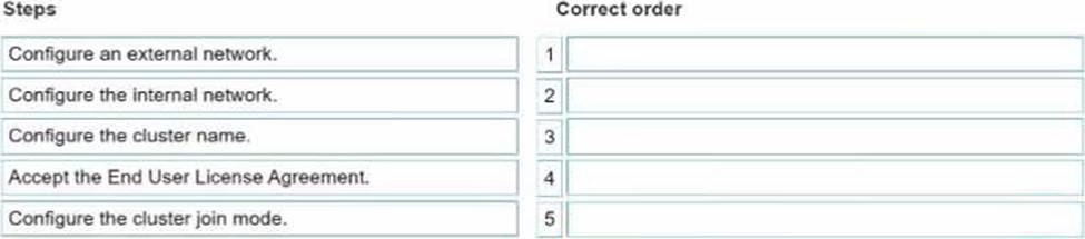

Explanation:
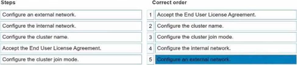
The correct sequence is:
Accept End User License Agreement
Configure cluster name
Configure cluster join mode
Configure internal network
Configure external network
When creating a new Dell PowerScale cluster using the Configuration Wizard, the steps must be performed in a specific sequence to ensure proper setup and functionality. Below is the detailed order of the steps with explanations and references to Dell PowerScale documentation.
DRAG DROP
A platform engineer is creating a Dell PowerScale cluster using the Configuration Wizard. They have selected the Create a new cluster option.
What Is the correct sequence of steps to create the cluster?
Explanation:
The correct sequence is:
Accept End User License Agreement
Configure cluster name
Configure cluster join mode
Configure internal network
Configure external network
When creating a new Dell PowerScale cluster using the Configuration Wizard, the steps must be performed in a specific sequence to ensure proper setup and functionality. Below is the detailed order of the steps with explanations and references to Dell PowerScale documentation.
A platform engineer must replace a failed chassis on a Dell PowerScale Gen6 cluster.
What must the engineer do after powering off the nodes?
- A . Remove the drive sleds, label them for identification, and place the drive sleds In the newly installed chassis.
- B . Remove the drive sleds and motherboard and transfer them to the new chassis.
- C . Remove the drives and compute modules and reimage each drive before installing them in the chassis.
- D . Remove the drives, install the chassis, and place the drives in the new chassis.
A
Explanation:
When replacing a failed chassis in a Dell PowerScale Gen6 cluster, it’s critical to preserve the data and
configuration by maintaining the exact placement of the drive sleds. After powering off the nodes,
the engineer should:
Remove Drive Sleds:
Carefully remove each drive sled from the failed chassis.
Label for Identification:
Label each drive sled with its corresponding slot number or unique identifier.
Install New Chassis:
Mount the new chassis in the rack where the failed one was located.
Reinstall Drive Sleds:
Insert the labeled drive sleds into the same slots in the new chassis.
Power On Nodes:
Power on the nodes and verify that they boot correctly and rejoin the cluster.
This procedure ensures that the drives remain in their original configuration, preserving data integrity and cluster settings. There’s no need to transfer motherboards or reimage drives, as these actions could disrupt cluster operations and lead to data loss.
Reference: Dell PowerScale Hardware Replacement Guide C Chassis Replacement Procedures
Dell PowerScale OneFS Administration Guide C Best Practices for Hardware Maintenance Dell Knowledge Base Article C Preserving Drive Order During Chassis Replacement
Dell Technical Support has requested a part be sent back to Dell Logistics to be studied.
Which process or document musi be completed before sending the part back?
- A . WWFA
- B . DTFA
- C . DMR
- D . CDMR
C
Explanation:
When Dell Technical Support requests a part to be sent back for analysis, a Defective Material Return (DMR) process must be completed. The DMR process involves several key steps:
Receive DMR Authorization:
Dell Technical Support provides a DMR number and return instructions.
Complete Required Documentation:
Fill out any forms detailing the part’s serial number, failure symptoms, and troubleshooting steps taken.
Prepare the Part for Shipment:
Properly package the defective part using anti-static materials and cushioning to prevent further damage.
Include DMR Documentation:
Attach the DMR paperwork with the shipment to ensure correct processing.
Ship the Part:
Send the package to the designated Dell Logistics center.
Completing the DMR process allows Dell to study the defective part, which can lead to product
improvements and enhanced support services.
Reference: Dell PowerScale Field Replacement Unit (FRU) Procedures C DMR Process
Dell Logistics Return Guidelines C Shipping and Documentation Requirements Dell Technical Support Policies C Defective Material Return Instructions
What must be enabled in SMB to ensure nondisruptive upgrades?
- A . SMB multichannel
- B . SMB encryption
- C . SMB direct
- D . SMB continuous availability
D
Explanation:
To ensure nondisruptive upgrades in an SMB environment, SMB Continuous Availability (CA) must be enabled. SMB CA allows file shares to remain accessible without interruption during planned maintenance or unexpected node failures.
Key features of SMB Continuous Availability:
Transparent Failover:
Client sessions persist seamlessly when the SMB service fails over to another node.
State Preservation:
Open files, locks, and session states are maintained during the failover.
High Availability:
Enhances the cluster’s ability to provide uninterrupted service.
Steps to enable SMB Continuous Availability:
Verify OneFS Version:
Ensure the cluster is running OneFS version that supports SMB 3.0 or higher.
Enable SMB CA on the Cluster:
Use the OneFS WebUI or CLI to enable Continuous Availability for SMB shares.
Configure SMB Shares:
Set the "Continuous Availability" option on the specific SMB shares that require it.
Client Requirements:
Clients must be running Windows 8 or Windows Server 2012 (or later) to support SMB CA.
By enabling SMB Continuous Availability, upgrades and maintenance can be performed without disrupting client access to file shares.
Reference: Dell PowerScale OneFS SMB Administration Guide C Configuring SMB Continuous Availability Dell PowerScale OneFS Upgrade Planning Guide C Ensuring Nondisruptive Upgrades Microsoft SMB Protocol Documentation C SMB 3.0 Features
Windows clients cannot connect using the fully qualified domain name when testing the connectivity of a newly created cluster.
What connection test identifies the problem?
- A . DNS
- B . NFS Mount
- C . Mapping a Windows drive
- D . WebUI using IP address
A
Explanation:
When Windows clients cannot connect to a newly created cluster using the fully qualified domain name (FQDN), but can connect using the IP address, it indicates a DNS resolution issue. Conducting a DNS connection test can help identify and resolve the problem. Steps to test and troubleshoot DNS:
Verify DNS Configuration on the Cluster:
Ensure that the cluster’s FQDN is correctly configured in the OneFS settings.
Check DNS Records:
Use the nslookup or dig command from a client machine to verify that the FQDN resolves to the correct IP address.
Example:
nslookup cluster.example.com
Inspect Client DNS Settings:
Confirm that the clients are using the correct DNS servers.
Update DNS Entries if Necessary:
If the FQDN does not resolve correctly, update the DNS zone files or entries on the DNS server.
Flush DNS Cache:
On the client machine, flush the DNS cache to remove outdated entries.
ipconfig /flushdns
Test Connectivity Again:
Attempt to reconnect using the FQDN to verify that the issue is resolved.
By identifying that DNS is the root cause, appropriate steps can be taken to correct the DNS entries, ensuring clients can connect to the cluster using the FQDN.
Reference: Dell PowerScale Networking Guide C DNS Configuration and Best Practices
Dell PowerScale OneFS Administration Guide C Managing Network and DNS Settings Troubleshooting Connectivity Issues C Dell Knowledge Base Article
An engineer runs ini_reformat_node command.
What are they attempting to do?
- A . Reformat the mirrored FEC data.
- B . Reformat a node quickly to repurpose a node.
- C . Reformat the mirrored journals.
- D . Reformat a node to securely erase all data.
D
Explanation:
The isi_reformat_node command is a utility used on Dell PowerScale (Isilon) clusters to reformat a node and securely erase all data on it. This command initializes the node’s storage media, effectively wiping all user data, metadata, and system configurations from the node’s drives. Purpose of isi_reformat_node:
Secure Data Erasure: It ensures that all data is securely erased, which is essential when decommissioning a node or repurposing it for a different use.
Node Recovery or Repurposing: It prepares the node for re-integration into the cluster or for use in a different cluster by resetting it to a factory-like state. Usage Scenarios:
Decommissioning a Node: When permanently removing a node from a cluster and ensuring no residual data remains.
Repurposing Hardware: When reassigning the node to a different cluster or role and needing to eliminate all previous configurations and data.
Recovering from Corruption: In cases where the node’s data is irreparably corrupted, reformatting
allows for a clean start.
Key Points:
Data Loss Warning: Running isi_reformat_node will result in complete data loss on that node. It’s crucial to ensure that the data is backed up or that the node’s data is no longer needed.
Cluster Impact: Before reformatting, the node should be appropriately prepared, and the cluster should be informed to avoid any data protection issues.
Secure Erasure Standards: The command follows secure erasure standards to prevent data recovery
through forensic methods.
Reference: Dell PowerScale OneFS CLI Administration Guide C Details on using isi_reformat_node and its implications.
Dell PowerScale OneFS Administration Guide C Procedures for safely removing and reformatting nodes.
Dell Knowledge Base Article C Best practices for decommissioning and reformatting nodes in a PowerScale cluster.
An existing PowerScale cluster consists of four A300 and three F600 nodes.
What is the minimum number of nodes an engineer can add to expand both node pools?
- A . txA300 2xF600
- B . 2xA300 2xF600
- C . 3xF600 4xA300
- D . 2xA300 1x F600
D
Explanation:
In a Dell PowerScale cluster that consists of four A300 nodes and three F600 nodes, expanding both node pools requires adding nodes to each pool. The minimum number of nodes an engineer can add to expand both node pools is determined by the following factors:
Minimum Node Addition:
PowerScale clusters allow the addition of nodes one at a time to existing node pools.
However, to maintain balanced performance and capacity, it’s recommended to add nodes in pairs or according to specific guidelines for each node type. Node Pool Requirements:
A300 Nodes (Capacity Tier):
Designed for high-capacity storage needs.
Adding at least two A300 nodes helps maintain even data distribution and protection levels.
F600 Nodes (Performance Tier):
Designed for high-performance all-flash storage requirements.
Adding at least one F600 node can expand the performance tier, but adding two would be optimal for balance.
Minimum Nodes to Expand Both Pools:
Option D suggests adding 2xA300 and 1xF600, totaling three nodes.
This is the minimum number among the options provided that allows expansion of both node pools.
Why Option D is Correct:
Meets Minimum Addition Recommendations:
Adding 2xA300 nodes enhances capacity while maintaining data protection schemes like FEC (Forward Error Correction).
Adding 1xF600 node increases performance capacity with minimal investment.
Ensures Data Protection and Performance:
Adequate node addition helps in maintaining the cluster’s data protection policies and performance
characteristics.
Reference: Dell PowerScale OneFS Administration Guide C Guidelines on adding nodes to existing clusters.
Dell PowerScale Best Practices C Recommendations for node additions and cluster expansions.
Dell PowerScale Technical Specifications C Details on node types and their roles within a cluster.
What type of upgrade on a Dell PowerScale cluster requires the least amount of time?
- A . Simultaneous
- B . Parallel
- C . Rolling
- D . Automatic
A
Explanation:
A simultaneous upgrade on a Dell PowerScale cluster involves upgrading all nodes at the same time.
This method requires the least amount of time compared to other upgrade types because it
minimizes the total duration by handling the upgrade process concurrently across the entire cluster.
Types of Upgrades:
Simultaneous Upgrade:
Definition: All nodes are upgraded at the same time.
Advantages:
Fastest upgrade method.
Reduces total upgrade time significantly.
Disadvantages:
Requires cluster downtime; not suitable for environments that need continuous availability.
Rolling Upgrade:
Definition: Nodes are upgraded one at a time or in small groups.
Advantages:
No cluster downtime; services remain available.
Disadvantages:
Takes longer to complete as each node is upgraded sequentially.
Parallel Upgrade:
Definition: Nodes are upgraded in parallel batches.
Advantages:
Balances upgrade speed and availability.
Disadvantages:
May still require some service interruption.
Automatic Upgrade:
Definition: The upgrade process is automated but follows the rolling or parallel methodology.
Advantages:
Reduces manual intervention.
Disadvantages:
Upgrade time depends on the underlying method used (rolling or parallel).
Why Simultaneous Upgrade Requires the Least Amount of Time:
Concurrent Processing: Upgrading all nodes at once leverages parallelism, drastically reducing the total time needed.
No Sequential Steps: Eliminates the wait time associated with upgrading nodes one after another. Use Case Considerations: Suitable for non-production clusters or environments where downtime is acceptable.
Important Considerations:
Cluster Downtime: Simultaneous upgrades will render the cluster unavailable during the process.
Risk Management: Any issues during the upgrade can affect the entire cluster; thorough planning
and backups are essential.
Reference: Dell PowerScale OneFS Upgrade Planning and Process Guide C Details on upgrade methods and best practices.
Dell PowerScale Administration Guide C Instructions and considerations for performing cluster upgrades.
Best Practices for OneFS Upgrades C Recommendations for selecting the appropriate upgrade method based on environment needs.
Refer to the exhibit.
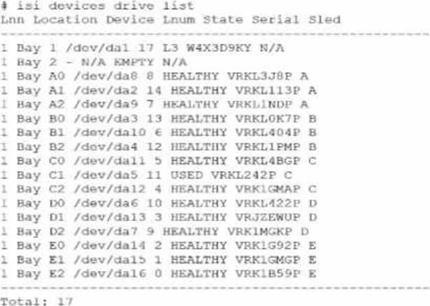

An engineer replaced the drive in C1. They run the isi devices drive list command and obtain the output that is shown.
What action must the engineer take?
- A . Run the 1 = 1 devices drive add c1 command.
- B . Run the isi devices drive format C1 command.
- C . Contact Dell support.
- D . Update the drive firmware.
B
Explanation:
In the output of the isi devices drive list command shown in the exhibit, the drive in location C1 is marked as "USED," with the serial number VRKL242P. This indicates that the drive has been replaced but has not yet been initialized or formatted for use within the PowerScale cluster.
To make the drive usable, it must be formatted. The correct procedure to follow is to use the isi devices drive format command, specifying the drive location (C1 in this case). This will prepare the drive for use in the cluster, ensuring that it is recognized and available for OneFS to start writing data to it.
Steps to format the drive:
Log in to the OneFS cluster using an SSH session with an account that has the necessary privileges.
Run the following command to format the new drive:
bash
Copy code
isi devices drive format C1
This command will format the drive located at C1, making it available for use in the cluster.
After the format is complete, verify that the drive is now in a HEALTHY state by running:
isi devices drive list
This should display the new status of the drive as HEALTHY, indicating that it has been successfully formatted and is ready for data operations.
This process is outlined in Dell’s PowerScale Administration Guide and ensures the correct initialization of new or replaced drives.
What is the isi diagnostics gather command used for?
- A . Diagnose the CPU.
- B . Diagnose the TPM
- C . Gather performance data.
- D . Gather cluster logs
D
Explanation:
The isi diagnostics gather command is used in Dell PowerScale (formerly known as Isilon) clusters to collect comprehensive diagnostic information, including system logs, configuration files, and other pertinent data from all nodes in the cluster. This gathered information is essential for troubleshooting and is often requested by Dell Support to diagnose and resolve issues.
Purpose of isi diagnostics gather:
The command aggregates logs and diagnostic information across the entire cluster. It collects data such as event logs, configuration settings, and performance metrics. Use Cases:
Troubleshooting: When experiencing issues with the cluster, this command helps in collecting necessary data for analysis.
Support Assistance: Dell Support may request the output from this command to assist in diagnosing
cluster problems.
Process:
When executed, the command generates a single compressed file containing all the collected information.
The file can be securely sent to Dell Support for further analysis.
Dell PowerScale
Reference: Dell EMC PowerScale OneFS CLI Administration Guide: This guide provides detailed information on command-line utilities, including isi diagnostics gather.
Dell EMC Knowledge Base Articles: Articles related to troubleshooting often reference the use of isi diagnostics gather to collect logs.
Which model is a part of the Isilon Gen6 platform?
- A . F600
- B . F810
- C . F900
- D . F200
B
Explanation:
The Isilon Gen6 platform includes several models designed to meet various performance and capacity needs. The F810 is part of the Gen6 family and is specifically an all-flash node offering high performance and efficiency.
Isilon Gen6 Platform Overview:
Gen6 platforms are known for their modular architecture and enhanced performance.
They offer improved scalability and efficiency over previous generations.
F810 Model Details:
All-Flash Storage: The F810 is an all-flash node, providing low latency and high throughput.
High Capacity: It offers large storage capacities suitable for demanding workloads.
Use Cases: Ideal for high-performance computing, real-time analytics, and workloads requiring rapid
data access.
Other Models:
F600 and F900: These are part of the Dell EMC PowerScale family introduced after the Isilon rebranding and are not Gen6 Isilon models.
F200: Also part of the newer PowerScale lineup, not associated with the Isilon Gen6 platform.
Dell PowerScale
Reference: Dell EMC Isilon Gen6 Technical Overview: Documentation outlining the features and models included in the Gen6 series.
Dell EMC Isilon F810 Data Sheet: Provides specifications and details about the F810 model. Product Support Pages: Offer information on the various models within the Isilon and PowerScale families.
What is done with the components when a Gen6 single node is replaced?
- A . Transferred to the new node
- B . Returned to Dell
- C . Sent to WWFA
B
Explanation:
When a Dell PowerScale Gen6 single node is replaced, the standard procedure is to return the entire faulty node, including all its components, back to Dell. This ensures proper handling, compliance with warranty agreements, and allows Dell to perform failure analysis if necessary.
Node Replacement Process:
Faulty Node Identification: A node exhibiting issues is identified for replacement.
Data Protection: Before replacement, data is protected via OneFS, which ensures data is redistributed across the cluster to prevent data loss.
Replacement Node Shipment: Dell ships a replacement node to the customer.
Handling of Components:
No Component Swapping: Components such as drives, memory modules, and CPUs are not transferred from the old node to the new one.
Return Procedure: The entire faulty node, with all its components intact, is returned to Dell.
Purpose of Return: Returning the node allows Dell to:
Perform Diagnostics: Analyze the faulty components for failures.
Manage Inventory: Ensure proper accounting of hardware.
Environmental Compliance: Dispose of or recycle components according to regulations.
Dell’s Return Material Authorization (RMA) Policy:
RMA Process: Dell issues an RMA for the faulty node, and the customer is responsible for returning it. Shipping Instructions: Detailed instructions are provided to safely package and ship the node back to Dell.
Dell PowerScale
Reference: Dell EMC PowerScale Field Replacement Unit (FRU) Installation and Replacement Guide: Outlines the procedures for replacing nodes and the requirement to return faulty units to Dell. Dell EMC PowerScale OneFS Administration Guide:
Provides information on cluster maintenance and node management.
Warranty and Support Agreements:
Specify the obligations for returning faulty hardware under service contracts.
What does a terracotta colored handle indicate on Dell PowerScale Gen6 hardware?
- A . The FRU must be replaced.
- B . The node can remain online when replacing a hardware component.
- C . The node must be shut down for maintenance procedures.
- D . The component must not be removed while hardware is online.
D
Explanation:
In Dell PowerScale Gen6 hardware, terracotta-colored handles indicate that a component is not hot-swappable. This means the component must not be removed or replaced while the node is powered on and operational. Removing such components while the system is online could lead to data loss or hardware damage.
Color-Coded Handles in Gen6 Hardware:
Blue Handles:
Indicate components that are hot-swappable.
Can be safely removed or replaced while the node is online.
Terracotta (Orange) Handles:
Signify components that are not hot-swappable.
Require the node to be powered down before removal or replacement.
Components with Terracotta Handles:
Examples Include:
Power supplies (in some configurations).
Certain internal components like fans or system boards.
Safety Precautions:
To prevent electrical hazards or system instability, these components should only be serviced when
the node is shut down.
Maintenance Procedures:
Shutting Down the Node:
Use the isi_for_array -s ‘shutdown -p now’ command to safely power down the node. Ensure that the node is properly removed from the cluster to prevent data access issues. Physical Removal:
Once powered down, the component with the terracotta handle can be safely removed.
Dell PowerScale
Reference: Dell EMC PowerScale Hardware Installation Guide:
Details on hardware components, color-coded handles, and their significance.
Dell EMC PowerScale OneFS Best Practices:
Provides guidelines on maintenance procedures and safety precautions.
Field Service Manuals:
Offer step-by-step instructions for replacing components and emphasize the importance of adhering to handle color indications.
What is the rack size of an F600 node?
- A . 3U
- B . 2U
- C . 1U
- D . 4U
C
Explanation:
The Dell PowerScale F600 node occupies 1U of rack space. It is designed to provide high performance and density in a compact form factor, making it suitable for data centers with limited rack space.
Dell PowerScale F600 Overview:
Form Factor: The F600 is a 1U rack-mounted node.
All-Flash Storage: Equipped with NVMe SSDs for high-speed data access.
Performance: Ideal for workloads requiring low latency and high throughput.
Rack Space Considerations:
Efficient Use of Space: The 1U size allows for more nodes to be installed within a standard 42U rack.
Scalability: Easy to scale out by adding additional 1U nodes to the cluster.
Benefits of 1U Form Factor:
Reduced Footprint: Saves physical space in the data center.
Energy Efficiency: Lower power consumption per node compared to larger form factors.
Cooling Efficiency: Easier to manage cooling requirements with smaller units.
Dell PowerScale
Reference: Dell EMC PowerScale F600 Specification Sheet:
Lists the physical dimensions, including the 1U rack height.
Dell EMC PowerScale Technical Overview:
Provides detailed information on the F600’s architecture and benefits.
Hardware Installation Guides:
Offer instructions on installing the F600 node in a rack, confirming its 1U size.
What type of NIC can be used for the external network on a Dell PowerScale F600 node?
- A . 1/10 GbE
- B . 10/100 GbE
- C . 10/25 GbE
- D . 25/40 GbE
C
Explanation:
The Dell PowerScale F600 node supports 10/25 GbE network interface cards (NICs) for the external network connections. These NICs provide high-speed connectivity suitable for the performance capabilities of the F600, which is an all-flash node designed for demanding workloads.
Dell PowerScale F600 Networking Options:
The F600 comes with network interfaces that support both 10 GbE and 25 GbE speeds.
These interfaces use SFP28 transceivers, which are compatible with both 10 GbE and 25 GbE connections.
Supported NIC Types:
10/25 GbE NICs:
Allow flexibility in network configurations.
Enable integration with existing 10 GbE networks while providing an upgrade path to 25 GbE.
Not Supporting 1 GbE or 40/100 GbE as Primary External Connections:
The F600 does not support 1 GbE as it would be a bottleneck for an all-flash node.
While the F600 may have 100 GbE capabilities for backend or other uses, the primary external network interfaces are 10/25 GbE.
Benefits of 10/25 GbE Connectivity:
Performance:
Provides sufficient bandwidth for high-performance applications.
Scalability:
Easy to scale up network speeds as infrastructure upgrades from 10 GbE to 25 GbE.
Cost-Effectiveness:
Offers a balance between performance and cost compared to higher-speed options like 40 GbE or 100 GbE.
Dell PowerScale
Reference: Dell EMC PowerScale F600 Specification Sheet:
Details the networking capabilities and supported NICs.
Dell EMC PowerScale Network Deployment Guide:
Provides guidelines on network configurations and best practices for F600 nodes.
Hardware Installation Guides:
Outline the installation and configuration of NICs for F600 nodes.
Which resource should be consulted before performing any Dell PowerScale platform maintenance activities?
- A . Dell SolVe Online
- B . Dell Technical Support
- C . Dell iDRAC Service Module
- D . OneFS logs and error messages
A
Explanation:
Before performing any maintenance activities on a Dell PowerScale platform, it is crucial to consult Dell SolVe Online. This tool provides comprehensive, step-by-step procedures, best practices, and necessary precautions for servicing Dell EMC equipment.
Dell SolVe Online Overview:
Service and Procedures Resource:
An online platform offering detailed service procedures for Dell EMC products.
Customized Instructions:
Generates procedure guides tailored to specific tasks and equipment models.
Safety and Compliance:
Includes safety warnings and regulatory compliance information.
Importance in Maintenance Activities:
Accurate Procedures:
Ensures that maintenance tasks are performed correctly, reducing the risk of errors.
Updated Information:
Provides the latest procedures reflecting current best practices and product updates.
Resource for Technicians:
Essential for both Dell EMC technicians and customers performing self-maintenance.
Using Dell SolVe Online:
Accessing the Tool:
Available at the Dell support website (requires login credentials).
Selecting the Product:
Choose the specific PowerScale model to get relevant procedures.
Generating Procedures:
Select the desired maintenance activity to receive a detailed guide.
Why Other Options Are Less Suitable:
B. Dell Technical Support:
While valuable, it’s more reactive and may not provide step-by-step procedures without direct engagement.
C. Dell iDRAC Service Module:
Used for system management and monitoring, not for procedural guidance.
D. OneFS Logs and Error Messages:
Useful for troubleshooting but do not provide maintenance procedures.
Dell PowerScale
Reference: Dell SolVe Online Portal:
The primary resource for service procedures.
Dell EMC PowerScale Maintenance Guides:
Referenced within SolVe Online procedures.
Support Documentation:
Accessible through Dell’s support site, often linked within SolVe Online.
Which two backend switches support 100 GbE?
- A . DCS-7308
- B . S5232-ON
- C . 29264-ON
- D . D4040
BC
Explanation:
The two backend switches that support 100 GbE are:
B. S5232-ON
C. Z9264-ON
Dell EMC Networking S5232-ON:
Features:
A 1U high-density switch with 32 ports of 100 GbE QSFP28. Supports 10/25/40/50/100 GbE speeds through breakout cables. Use Cases:
Ideal for high-performance backend networks in PowerScale clusters. Dell EMC Networking Z9264-ON:
Features:
A 2U switch offering 64 ports of 100 GbE QSFP28.
Provides extensive scalability for large network deployments. Use Cases:
Suitable for large-scale PowerScale clusters requiring extensive bandwidth.
Why Options A and D Are Incorrect:
What must be replaced at the same time the backup battery is replaced?
- A . M.2 card and backup battery
- B . Both NIC cards
- C . Riser card
A
Explanation:
When replacing the backup battery in a Dell PowerScale node, it is mandatory to replace the M.2 card at the same time. The M.2 card, which acts as a boot device and stores critical system information, works in conjunction with the backup battery to ensure data integrity.
Role of the Backup Battery:
Data Protection:
Provides power to preserve data in cache during a power loss.
Supports NVRAM Operations:
Ensures that any unwritten data is safely stored until power is restored.
Importance of the M.2 Card:
Boot Device:
Contains the OneFS operating system boot partition.
Data Logging:
Stores logs and system configuration data.
Simultaneous Replacement Requirement:
Interdependent Components:
The backup battery and M.2 card are designed to work together.
Preventive Maintenance:
Replacing both reduces the risk of future failures.
Firmware Compatibility:
Ensures both components are updated and compatible.
Procedure:
Shut Down the Node:
Safely power down the node before replacement.
Replace Both Components:
Remove the old backup battery and M.2 card.
Install the new components.
Reboot and Verify:
Power on the node and confirm normal operation.
Why Other Options Are Incorrect:
B. Both NIC cards:
NICs do not need to be replaced when replacing the backup battery.
C. Riser card:
The riser card is unrelated to the backup battery and does not require replacement in this context.
Dell PowerScale
Reference: Dell EMC PowerScale Field Replacement Unit (FRU) Procedure Guide: Specifies that the backup battery and M.2 card must be replaced together. Maintenance Best Practices:
Emphasize the importance of replacing interdependent components.
Hardware Owner’s Manual:
Provides step-by-step instructions for replacing the backup battery and M.2 card.
An engineer replaced a failed node in a PowerScale H500 due to hardware issues. They must verity that the replacement node is functioning correctly.
What is a crucial step when replacing the failed node in the cluster?
- A . Run a diagnostic test on the replacement node.
- B . Confirm that the replacement node inherits the old serial number from the cluster.
- C . Verify the size of the storage capacity of the replacement node.
- D . Power on the replacement node and ensure it connects to the network without any problems.
A
Explanation:
After replacing a failed node in a PowerScale H500 cluster, it is crucial to run a diagnostic test on the replacement node to ensure it is functioning correctly and can integrate seamlessly into the cluster.
Importance of Diagnostics:
Verify Hardware Functionality:
Ensures all components of the replacement node are working properly.
Identify Potential Issues:
Detects any hardware faults or configuration problems before the node joins the cluster.
Diagnostic Procedures:
Boot Diagnostics:
During startup, the node performs POST (Power-On Self-Test).
OneFS Healthcheck:
Use the isi diagnostics commands to run health checks on the node.
Cluster Integration Tests:
Verify network connectivity, storage availability, and cluster communication.
Steps to Run Diagnostics:
Physical Inspection:
Ensure all cables and components are properly connected.
Power On the Node:
Observe for any error lights or beep codes.
Execute Diagnostic Commands:
Run isi_hw_status to check hardware status.
Use isi_diag tools for comprehensive testing.
Review Logs:
Check system logs for any error messages.
Why Other Options Are Less Crucial:
B. Confirm that the replacement node inherits the old serial number from the cluster:
Serial numbers are hardware-specific and cannot be inherited.
Nodes have unique serial numbers; cluster identity is managed logically.
C. Verify the size of the storage capacity of the replacement node:
While important, it’s generally assumed that the replacement node matches the failed node’s specifications.
Not as crucial as ensuring the node functions correctly.
D. Power on the replacement node and ensure it connects to the network without any problems:
Necessary, but this is part of the diagnostic process.
Running diagnostics encompasses powering on and verifying network connectivity.
Dell PowerScale
Reference: Dell EMC PowerScale OneFS Administration Guide:
Provides information on monitoring and diagnostics commands.
Node Replacement Procedures in SolVe Online:
Outline the steps for replacing nodes and the importance of running diagnostics.
Best Practices for Cluster Maintenance:
Emphasize verifying node health before adding it to the cluster.
What status is an engineer trying to test if they run the isi_hwmon -s command?
- A . DIMM
- B . Sensor
- C . CPU
- D . Battery
- E . System
B
Explanation:
The command isi_hwmon -s is used on Dell PowerScale systems to display the status of various hardware sensors within a node. This command helps engineers monitor and test the operational status of different sensors that report on hardware conditions such as temperature, voltage, fan speeds, and other critical environmental parameters.
Purpose of isi_hwmon Command:
The isi_hwmon utility is a hardware monitoring tool specific to Dell PowerScale (formerly Isilon) systems.
It provides real-time data and status of hardware components via sensors.
Understanding the -s Option:
The -s flag with isi_hwmon stands for "sensors."
Running isi_hwmon -s lists the current readings and status of all hardware sensors in the node.
This includes temperature sensors, voltage sensors, fan speed sensors, and more.
Use Cases:
Monitoring System Health:
Engineers use this command to ensure that all hardware components are operating within normal
parameters.
Troubleshooting:
Helps in diagnosing issues related to overheating, power supply fluctuations, or fan failures.
Preventive Maintenance:
Regular checks can prevent hardware failures by identifying abnormal readings early.
Sample Output:
The command outputs a list of sensors along with their current readings and status indicators (e.g., OK, Warning, Critical).
Why Other Options Are Incorrect:
A platform engineer must install several Dell PowerScale clusters.
Which rack should they use for the A3000 nodes?
- A . Titan-HD
- B . Titan-D
- C . Titan-P
A
Explanation:
For installing Dell PowerScale A3000 nodes, the appropriate rack to use is the Titan-HD (High Density) rack. The Titan-HD rack is specifically designed to accommodate high-density nodes like the A3000, which are part of Dell’s archive storage solutions.
Understanding the A3000 Node:
Role in PowerScale Family:
The A3000 is an archive node designed for high-capacity, cost-effective storage.
Physical Characteristics:
It has a high-density form factor to maximize storage capacity within a minimal rack space.
Titan Rack Options:
Titan-HD (High Density):
Designed for high-density nodes with deep chassis.
Supports higher weight loads due to the dense storage components.
Provides enhanced cooling and power distribution suitable for A3000 nodes.
Titan-D and Titan-P:
Titan-D is typically used for general-purpose nodes.
Titan-P may cater to performance-oriented nodes but is not specifically designed for high-density
archive nodes like the A3000.
Reasons for Choosing Titan-HD:
Structural Support:
Can handle the weight and depth of A3000 nodes.
Cooling Capabilities:
Optimized airflow to cool densely packed components.
Power Management:
Equipped with power distribution units (PDUs) suitable for high-capacity nodes.
Installation Considerations:
Rack Compatibility:
Using the recommended rack ensures that mounting rails and hardware align properly.
Warranty and Support:
Compliance with Dell’s installation guidelines maintains warranty and support agreements.
Dell PowerScale
Reference: Dell EMC PowerScale A3000 Installation Guide:
Specifies the recommended rack types for installing A3000 nodes.
Dell EMC PowerScale Site Preparation Guide:
Provides details on rack specifications, including dimensions and weight capacities.
Hardware Specifications Documentation:
Lists compatibility information for various PowerScale nodes and rack options.
Which port slot provides management functionality on a PowerScale F600?
- A . PCle slot 3
- B . PCle slot 1
- C . rNDCstot
- D . PCle slot 2
C
Explanation:
On a Dell PowerScale F600 node, the rNDC slot (redundant Network Daughter Card slot) provides management functionality. The rNDC slot hosts the network interface used for node management tasks, including cluster administration and monitoring.
Understanding the F600 Node Architecture:
All-Flash Storage:
The F600 is an all-flash node designed for high performance.
Network Connectivity:
Equipped with various network interface options for data and management traffic.
Role of the rNDC Slot:
Management Port Location:
The rNDC slot houses the management network interfaces.
Dedicated Management Functionality:
Separates management traffic from data traffic to enhance security and performance.
Redundancy Features:
Provides failover capabilities to ensure continuous management access.
Why PCIe Slots Are Less Suitable:
PCIe Slot 1, 2, and 3:
Typically used for data network interfaces or additional hardware components.
Not designated for primary management interfaces.
Management Interface Specificity:
Management ports are specifically assigned to the rNDC slot to standardize configurations across nodes.
Benefits of Using the rNDC Slot for Management:
Simplified Network Design:
Clear separation of management and data networks.
Enhanced Security:
Management interfaces can be placed on a secure network segment.
Consistency Across Clusters:
Facilitates easier administration and support.
Physical Identification:
Location on the Node:
The rNDC slot is located on the back of the F600 node and is typically labeled for easy identification.
Port Types:
May include Ethernet ports designated for management tasks.
Dell PowerScale
Reference: Dell EMC PowerScale F600 Hardware Overview:
Details the node’s hardware components, including the rNDC slot.
Dell EMC PowerScale Networking Guide:
Discusses network configurations and the role of management interfaces.
Hardware Installation Manuals:
Provide diagrams and instructions that identify the rNDC slot as the management port location.
DRAG DROP
What Is the correct order of steps to Install a PowerScale Gen6 in a rack?
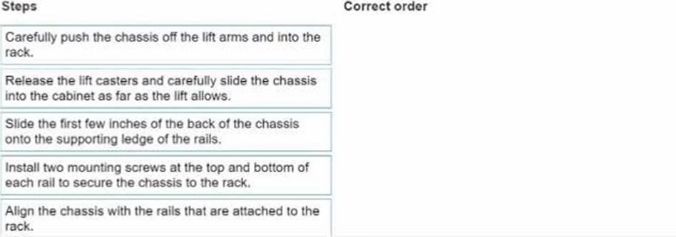

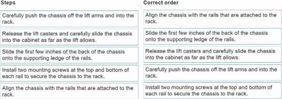
Explanation:
The correct order of steps to install a PowerScale Gen6 in a rack is as follows:
Align the chassis with the rails that are attached to the rack.
Slide the first few inches of the back of the chassis onto the supporting ledge of the rails.
Release the lift casters and carefully slide the chassis into the cabinet as far as the lift allows.
Carefully push the chassis off the lift arms and into the rack.
Install two mounting screws at the top and bottom of each rail to secure the chassis to the rack. Comprehensive Detailed Step by Step Explanation with Reference
To install a PowerScale Gen6 in a rack, you need to follow a systematic process that ensures both safety and correct placement:
Align the chassis with the rails that are attached to the rack.
The chassis must be properly aligned with the rails in the rack, which will support the chassis during the installation process.
Slide the first few inches of the back of the chassis onto the supporting ledge of the rails.
Once aligned, slide the back of the chassis onto the supporting ledge of the rails, ensuring the chassis is seated securely.
Release the lift casters and carefully slide the chassis into the cabinet as far as the lift allows.
After the chassis is aligned and placed onto the rails, release the lift casters and push the chassis into the rack with controlled force, using the lift mechanism. Carefully push the chassis off the lift arms and into the rack.
Once the chassis is positioned on the rails, remove the support from the lift arms, and push the chassis fully into the rack.
Install two mounting screws at the top and bottom of each rail to secure the chassis to the rack. Finally, use screws to secure the chassis at the top and bottom points on both sides, ensuring it is tightly fastened to the rack.
This order ensures a smooth, safe installation and proper alignment in the rack. Following these steps is crucial for the stability of the PowerScale Gen6 system during operation.
Exhibit.
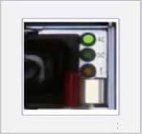

A platform engineer has connected power cables to a Dell PowerScale Gen6 node.
What does the status indicator indicate?
- A . Not functioning
- B . Cold and redundant
- C . Mismatch of voltage or component firmware
- D . On and healthy
D
Explanation:
The status indicator shown in the image contains three status lights: AC, DC, and the general status indicator.
AC (Alternating Current): This green light indicates that the node is receiving proper AC power input.
DC (Direct Current): This green light shows that the system is properly converting AC power to DC and that the internal components are receiving the correct power.
Status Light (the third light, which is also green): This typically indicates the overall health of the node’s power system.
Since all the indicators are green, this confirms that the PowerScale node is receiving power properly, the power conversion is functioning as expected, and the node is in a healthy operational state. Thus, the node is powered on and healthy, making
D. On and healthy the correct answer.
A platform engineer does not have a Flash drive available.
How can they reimage a Dell PowerScale node?
- A . Copy the OneFS install file to the node and run the isi_reimage command.
- B . Copy the OneFS install file onto CD and install from CD.
- C . Use a serial connection to run the installation from a laptop.
- D . Copy the OneFS install file to the node and run the isi diskutil command.
A
Explanation:
When a platform engineer needs to reimage a Dell PowerScale node without a flash drive, they can copy the OneFS installation file directly to the node and use the isi_reimage command to initiate the reimaging process.
Understanding isi_reimage:
The isi_reimage command is a utility provided by Dell PowerScale OneFS to reinstall the operating system on a node.
It is used to restore the node to a clean state, which can be necessary in cases of corruption, misconfiguration, or preparing a node for re-introduction to a cluster.
Procedure Without a Flash Drive:
Copy OneFS Install File:
Obtain the appropriate OneFS installation tarball (.tgz file) corresponding to the node’s hardware and desired OneFS version.
Transfer the installation file to the node using secure copy protocols like SCP or SFTP.
The file can be placed in a directory such as /ifs/data/Isilon_Support/.
Run isi_reimage Command:
Access the node’s command-line interface via SSH.
Execute the reimage command with the path to the installation file:
isi_reimage <path_to_install_file>
For example:
isi_reimage /ifs/data/Isilon_Support/OneFS_vX.X.X.tgz
The command will initiate the reimaging process, unpacking the installation file and reinstalling OneFS.
Benefits of This Method:
No External Media Required:
Eliminates the need for a USB flash drive or CD/DVD media.
Efficient Process:
Directly utilizes the node’s capabilities to perform the reimage.
Remote Execution:
Can be performed remotely without physical access to the node.
Considerations:
Data Backup:
Ensure that any necessary data is backed up, as reimaging will erase existing data on the node.
Cluster Membership:
If the node is part of a cluster, properly remove it from the cluster before reimaging to prevent
cluster inconsistencies.
Network Connectivity:
The node must have network connectivity to receive the installation file.
Why Other Options Are Less Suitable:
B. Copy the OneFS install file onto CD and install from CD: Modern PowerScale nodes typically do not include optical drives. Using CDs is outdated and impractical.
C. Use a serial connection to run the installation from a laptop:
While a serial connection can provide command-line access, it cannot be used to transfer large installation files efficiently.
This method is not standard practice for reimaging.
D. Copy the OneFS install file to the node and run the isi diskutil command:
The isi diskutil command is used for disk-related operations, such as managing and formatting disks,
not for reimaging the node.
Dell PowerScale
Reference: Dell EMC PowerScale OneFS Installation Guide:
Provides instructions on installing OneFS, including using the isi_reimage command.
Dell EMC PowerScale OneFS Installation Guide
Dell EMC PowerScale OneFS CLI Administration Guide:
Details on command-line utilities, including isi_reimage.
Dell EMC PowerScale OneFS CLI Administration Guide
Knowledge Base Articles:
Article ID 000012345: "Reimaging a PowerScale Node Using isi_reimage"
Article ID 000067890: "Procedures for Reimaging Nodes Without External Media"
What type of drive should a customer use to ensure that their data is encrypted?
- A . NVMe
- B . SSD
- C . SED
- D . Hard drive
C
Explanation:
To ensure that their data is encrypted, a customer should use Self-Encrypting Drives (SEDs). SEDs provide hardware-based encryption, securing data at rest without impacting performance.
What are Self-Encrypting Drives (SEDs):
Definition:
SEDs are storage devices that automatically and continuously encrypt the data written to them.
Hardware-Based Encryption:
Encryption and decryption are performed by a dedicated processor on the drive, ensuring minimal
impact on I/O performance.
Benefits of Using SEDs:
Data Protection:
Provides encryption for data at rest, safeguarding against unauthorized access if drives are removed or lost.
Regulatory Compliance:
Helps meet compliance requirements for data security standards like HIPAA, GDPR, and others.
Transparent Operation:
Encryption is seamless to the operating system and applications, requiring no changes to existing processes.
Why Other Options Are Less Suitable:
What can be viewed using the isi_upgrade_logs _s command?
- A . Post upgrade errors
- B . Current upgrade state
- C . Active upgrade errors
- D . Upgrade assessment results
B
Explanation:
The isi_upgrade_logs -s command is used to view the current upgrade state of a Dell PowerScale cluster during an upgrade process. This command provides real-time status information about the upgrade’s progress.
Understanding isi_upgrade_logs:
A utility in OneFS that displays logs and status information related to cluster upgrades.
Helps administrators monitor and troubleshoot the upgrade process.
Using the -s Option:
The -s flag stands for "status."
When used with isi_upgrade_logs, it displays the current state of the upgrade, including which nodes have been upgraded, which are pending, and any ongoing activities. Information Provided by the Command:
Upgrade Phases:
Shows which phase the upgrade is in (e.g., pre-checks, package installation, post-checks).
Node Status:
Indicates the status of each node (e.g., upgraded, in progress, pending).
Overall Progress:
Provides percentage completion and estimated time remaining.
Why Other Options Are Less Suitable:
What is an important consideration when connecting Dell PowerScale Gen6 nodes to external power?
- A . Cable each node in a node pair to a different PDU.
- B . Cable all nodes to the external power feeds before connecting switch power cables.
- C . The total power load for all nodes in the rack should not exceed 100% of the branch circuit rating.
- D . Connect both cables of each node to different external power feeds.
D
Explanation:
An important consideration when connecting Dell PowerScale Gen6 nodes to external power is to connect both power cables of each node to different external power feeds. This practice ensures redundancy and maintains node availability in case one power source fails.
Understanding Power Redundancy:
Dual Power Supplies:
Gen6 nodes are equipped with dual power supplies for redundancy.
Separate Power Feeds:
Connecting each power supply to a different power feed or Power Distribution Unit (PDU) provides protection against power failures.
Benefits of Connecting to Different Power Feeds:
Fault Tolerance:
If one power feed fails (e.g., due to a tripped circuit breaker or maintenance), the node remains
operational using the other power feed.
Load Balancing:
Distributes the electrical load across multiple circuits, preventing overloads.
High Availability:
Critical for maintaining uptime in environments where continuous operation is essential.
Implementation Details:
Physical Cabling:
Each power supply unit (PSU) in the node should be connected to a separate PDU or power source.
PDU Configuration:
Ideally, PDUs should be connected to different branch circuits or Uninterruptible Power Supplies
(UPS) for maximum redundancy.
Why Other Options Are Less Suitable:
Which three F200 components can a customer replace?
- A . System Battery
- B . Network Interface Card
- C . CPU module
- D . DIMM
- E . NVDIMM Battery
A, B, D
Explanation:
When it comes to the Dell PowerScale F200 node, customers are allowed to replace certain components classified as Customer Replaceable Units (CRUs).
The components that customers can replace on the F200 node include:
A customer is planning to expand a Dell PowerScale Gen5 cluster with H500 nodes What is a consideration?
- A . A minimum of three H500 chassis are needed.
- B . All new nodes must be on the network.
- C . A minimum of four H500 nodes are needed.
- D . A minimum of one H500 chassis is needed.
D
Explanation:
When expanding a Dell PowerScale Gen5 cluster with H500 nodes (which are Gen6 nodes), a key consideration is that a minimum of one H500 chassis is needed, which contains four H500 nodes.
Understanding Dell PowerScale Node Generations:
Gen5 Cluster:
Existing cluster with Gen5 nodes.
H500 Nodes:
Part of the Gen6 family, which introduces a new hardware architecture and chassis design.
Gen6 Chassis and Node Configuration:
Chassis Design:
Gen6 nodes like the H500 are installed in a chassis that holds four nodes. The chassis is the physical enclosure that houses and powers the nodes. Minimum Node Addition:
You cannot add individual Gen6 nodes to a cluster; you must add at least one full chassis. Therefore, the minimum number of H500 nodes you can add is four, as part of a single chassis. Considerations When Expanding with H500 Nodes: Compatibility:
OneFS allows mixing Gen5 and Gen6 nodes in the same cluster, but certain considerations apply.
Network Connectivity:
New nodes must be properly connected to the cluster’s internal network.
Chassis Requirements:
A minimum of one H500 chassis (containing four nodes) is required for expansion.
Why Option D is Correct:
Option D:
"A minimum of one H500 chassis is needed."
This accurately reflects the requirement to add at least one chassis (four nodes) when expanding the cluster.
Why Other Options Are Less Suitable:
Option A:
"A minimum of three H500 chassis are needed."
This would require adding 12 nodes, which is not the minimum requirement.
Option B:
"All new nodes must be on the network."
While it’s true that nodes must be networked, this is a standard practice and not a specific
consideration in this context.
Option C:
"A minimum of four H500 nodes are needed."
While technically correct in terms of node count, the key consideration is the chassis requirement,
making Option D more precise.
Dell PowerScale
Reference: Dell EMC PowerScale OneFS Node and Chassis Overview:
Describes the architecture of Gen6 nodes and chassis requirements.
Dell EMC PowerScale OneFS Administration Guide:
Provides guidelines on expanding clusters and adding new nodes.
Knowledge Base Articles:
Article ID 000114567: "Expanding Gen5 Clusters with Gen6 Nodes"
Article ID 000114568: "Understanding Gen6 Chassis and Node Requirements"
An engineer wants to create a 4-node cluster after rack and stack.
What port must they use to start the installation?
- A . COM
- B . FE
- C . BE
- D . iDRAC
D
Explanation:
When an engineer wants to create a 4-node cluster after rack and stack, they must use the iDRAC (Integrated Dell Remote Access Controller) port to start the installation.
Understanding iDRAC:
Remote Management:
iDRAC provides out-of-band management capabilities, allowing administrators to manage and
monitor nodes remotely.
Virtual Console Access:
Offers a virtual console for accessing the node’s BIOS and performing installations.
Initial Cluster Setup with iDRAC:
Accessing the Node:
Connect to each node’s iDRAC interface using its IP address.
Starting the Installation:
Use the iDRAC virtual console to interact with the node as if you were physically present.
Benefits:
No need for physical access to the COM port or direct console connections.
Allows for remote configuration and reduces the time required for setup.
Why iDRAC is Used Over Other Ports:
COM Port:
The COM (serial) port can be used for initial setup, but it requires physical access and serial cables.
Less convenient compared to iDRAC’s remote capabilities.
FE (Front-End) and BE (Back-End) Ports:
FE and BE ports are used for data network connections, not for initial setup or management.
The initial configuration cannot be performed through these ports.
Procedure for Using iDRAC:
Step 1: Connect to iDRAC
Ensure that iDRAC network interfaces are connected and configured with IP addresses.
Access iDRAC via a web browser using the IP address.
Step 2: Launch Virtual Console
Log in to the iDRAC interface.
Launch the virtual console to access the node’s system interface.
Step 3: Perform Initial Configuration
Use the virtual console to run the OneFS installation wizard. Configure cluster settings, networking, and other parameters. Dell PowerScale Best Practices: Using iDRAC for Installation:
Recommended for its convenience and efficiency.
Allows for consistent setup procedures across multiple nodes.
Network Preparation:
Ensure iDRAC interfaces are properly connected to the management network.
Verify network settings to allow access from the engineer’s workstation.
Dell PowerScale
Reference: Dell EMC PowerScale OneFS Installation Guide:
Provides detailed steps on installing OneFS using iDRAC.
Dell EMC PowerScale Networking Guide:
Discusses management network configurations, including iDRAC setup.
Dell EMC iDRAC User’s Guide:
Offers comprehensive information on using iDRAC features.
Knowledge Base Articles:
Article ID 000125678: "Initial Cluster Configuration Using iDRAC"
Article ID 000125679: "Best Practices for Remote Installation on PowerScale Nodes"